Home › Power Source / Network › POWER DISTRIBUTION › POWER INTEGRATION SYSTEM › from 2020.07
NM36W0E _57 Power Source / Network _088296 POWER DISTRIBUTION _0420971 POWER INTEGRATION SYSTEM CO CONTROL F

POWER DISTRIBUTION  POWER INTEGRATION SYSTEM  CONTROL  ELECTRIC POWER CONTROL  


FUNCTION OF MAIN COMPONENTS


*1: Models without entry and start system

*2: Models with entry and start system

Components Function
Ignition Switch*1
·

Receives power supply mode change operations from the driver.

·

Performs on/off operation for the IGP relay and IGR relay.


Engine Switch (Gasoline Models)*2/Power Switch (HV Models)*2 Receives power supply mode change operations from the driver.
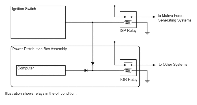
IGP Relay Turns the power supply to motive force generating systems on/off.
Power Distribution Box Assembly
·

Uses the vehicle speed signal to determine whether the vehicle is moving or stopped, and when there is an emergency shutdown operation while the vehicle is in motion, it controls the IGR relay to remain at ON continuously.*1

·

Built into the IGR relay.


IGR Relay Built into the power distribution box assembly, and turns the power supply to other systems on/off.
Certification ECU (Smart Key ECU Assembly)*2 Uses the vehicle speed signal to determine whether the vehicle is moving or stopped, and when there is an emergency shutdown operation while the vehicle is in motion, it controls the IGR relay to remain at ON continuously.
Main Body ECU (Multiplex Network Body ECU) Receives the vehicle speed signal and sends it to the power distribution box assembly.*1
Skid Control ECU Sends the vehicle speed signal.
Central Gateway ECU (Network Gateway ECU) Relays the signal between the CAN communication lines.


SYSTEM CONTROL


a.

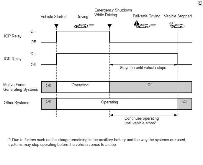
In a situation where the vehicle is making an "emergency shutdown while driving", the supply of power is stopped only to the systems which generate motive force, and supply of power to other systems continues until the vehicle comes to a stop.


b.

By adopting a scene-based power supply system, in the event of an "emergency shutdown while driving", the other systems which were traditionally shut down together with the motive force-generating systems can instead continue to operate until the vehicle comes to a stop.

NOTICE:
·

The functioning of the scene-based power supply does not guarantee that systems will be able to continue operating until the vehicle comes to a stop.

·

Due to factors such as the charge remaining in the auxiliary battery and the way the systems are used, systems may stop operating before the vehicle comes to a stop. For this reason, do not perform an emergency shutdown while driving except in an emergency.


Y251592E01
1.438,0.5 2.615,0.875 1.177,0.375 10 false Vehicle Started 2.698,0.5 3.438,0.854 0.74,0.354 10 false Driving 3.333,0.271 4.698,0.646 1.365,0.375 10 false Emergency Shutdown While Driving 4.688,0.479 5.865,0.854 1.177,0.375 10 false Fail-safe Driving 5.792,0.479 6.969,0.854 1.177,0.375 10 false Vehicle Stopped 0.146,1.188 1.323,1.563 1.177,0.375 10 false IGP Relay 0.135,1.99 1.313,2.365 1.177,0.375 10 false IGR Relay 0.115,2.906 1.396,3.344 1.281,0.438 10 false Motive Force Generating Systems 0.135,3.542 1.25,3.813 1.115,0.271 10 false Other Systems 2.531,2.917 3.708,3.292 1.177,0.375 10 false Operating 3.573,3.521 4.75,3.896 1.177,0.375 10 false Operating 4.229,2.302 6.229,2.688 2,0.385 10 false Stays on until vehicle stops 4.396,4.094 5.646,4.49 1.25,0.396 10 false Continues operating until vehicle stops* 0.302,4.854 6.698,5.25 6.396,0.396 10 false *: Due to factors such as the charge remaining in the auxiliary battery and the way the systems are used, systems may stop operating before the vehicle comes to a stop. 1.073,1.021 1.438,1.385 0.365,0.365 10 false On 1.073,1.813 1.438,2.177 0.365,0.365 10 false On 1.083,1.396 1.448,1.76 0.365,0.365 10 false Off 1.083,2.198 1.448,2.563 0.365,0.365 10 false Off 1.615,2.938 1.979,3.302 0.365,0.365 10 false Off 1.615,3.5 1.979,3.865 0.365,0.365 10 false Off 6.438,3.5 6.802,3.865 0.365,0.365 10 false Off 5.208,2.906 5.573,3.271 0.365,0.365 10 false Off


FUNCTION


·

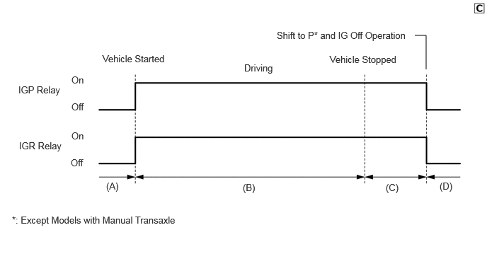
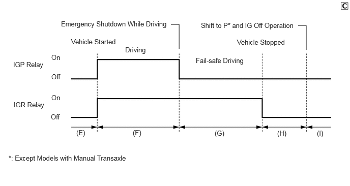
The scene-based power supply system controls the IGP relay and IGR relay according to vehicle conditions.


a.

Models without Entry and Start System

i.

IGP/IGR Relay Timing Chart: Normal Conditions
Y251593E01
6.104,0.521 6.271,0.521 6.271,0.521 6.271,1.021 true 1.51,0.781 2.802,1.021 1.292,0.24 10 false Vehicle Started 3.594,0.917 4.083,1.198 0.49,0.281 10 false Driving 4.854,0.792 6.146,1.031 1.292,0.24 10 false Vehicle Stopped 4.073,0.438 6.167,0.76 2.094,0.323 10 false Shift to P* and IG Off Operation 0.271,1.24 1.563,1.479 1.292,0.24 10 false IGP Relay 0.281,2.063 1.573,2.302 1.292,0.24 10 false IGR Relay 0.177,3.156 3.406,3.479 3.229,0.323 10 false *: Except Models with Manual Transaxle 1.052,1.094 1.583,1.396 0.531,0.302 10 false On 1.052,1.49 1.583,1.792 0.531,0.302 10 false Off 1.042,2.313 1.573,2.615 0.531,0.302 10 false Off 1.052,1.917 1.583,2.219 0.531,0.302 10 false On 1.563,2.656 2.094,2.958 0.531,0.302 10 false (A) 3.573,2.677 4.104,2.979 0.531,0.302 10 false (B) 5.677,2.677 6.208,2.979 0.531,0.302 10 false (C) 6.469,2.656 7,2.958 0.531,0.302 10 false (D)


ii.

IGP/IGR Relay Timing Chart: Emergency Shutdown While Driving
Y251594E01
6.104,0.521 6.271,0.521 6.271,0.521 6.271,1.021 true 3.5,0.5 3.667,0.5 3.667,0.5 3.667,1 true 1.458,0.771 2.75,1.01 1.292,0.24 10 false Vehicle Started 2.563,0.938 3.854,1.177 1.292,0.24 10 false Driving 4.854,0.781 6.146,1.021 1.292,0.24 10 false Vehicle Stopped 4.115,0.438 6.208,0.76 2.094,0.323 10 false Shift to P* and IG Off Operation 0.271,1.24 1.563,1.479 1.292,0.24 10 false IGP Relay 0.281,2.063 1.573,2.302 1.292,0.24 10 false IGR Relay 0.177,3.156 3.406,3.479 3.229,0.323 10 false *: Except Models with Manual Transaxle 1.052,1.094 1.583,1.396 0.531,0.302 10 false On 1.052,1.49 1.583,1.792 0.531,0.302 10 false Off 1.042,2.313 1.573,2.615 0.531,0.302 10 false Off 1.052,1.917 1.583,2.219 0.531,0.302 10 false On 1.563,2.635 2.094,2.938 0.531,0.302 10 false (E) 2.719,2.635 3.25,2.938 0.531,0.302 10 false (F) 5.677,2.646 6.208,2.948 0.531,0.302 10 false (H) 6.49,2.646 7.021,2.948 0.531,0.302 10 false (I) 1.25,0.406 3.5,0.708 2.25,0.302 10 false Emergency Shutdown While Driving 4.396,2.646 4.927,2.948 0.531,0.302 10 false (G) 4.01,1.156 5.302,1.396 1.292,0.24 10 false Fail-safe Driving


iii.

Relay Status for Timing Charts Shown Above
Y251595E02
5.771,2.25 7.063,2.49 1.292,0.24 10 false to Other Systems 5.74,0.479 7.031,0.865 1.292,0.385 10 false to Motive Force Generating Systems 4.354,1.021 5.646,1.26 1.292,0.24 10 false IGP Relay 4.375,2.802 5.667,3.042 1.292,0.24 10 false IGR Relay 0.177,3.302 3.406,3.625 3.229,0.323 10 false Illustration shows relays in the off condition. 0.438,0.229 2.688,0.531 2.25,0.302 10 false Ignition Switch 0.635,2.385 1.927,2.625 1.292,0.24 10 false Computer 0.448,1.688 2.74,1.979 2.292,0.292 10 false Power Distribution Box Assembly

Status in Timing Charts Above Relay Name Relay Status Component Carrying Coil Energization Inside Relay Power Supply Destination
(A), (D), (E), (H), (I) IGP Relay Off - -
IGR Relay Off - -
(B), (C), (F) IGP Relay On Ignition Switch Motive Force Generating Systems
IGR Relay On Ignition Switch and Power Distribution Box Assembly Other Systems
(G)* IGP Relay Off - -
IGR Relay On Power Distribution Box Assembly Other Systems

HINT:

*: For vehicles without manual transaxles, even when an emergency shutdown while driving is not being performed, there are some situations when the IGP relay would be off while the IGR relay is on.


b.

Models with Entry and Start System

i.

IGP/IGR Relay Timing Chart: Normal Conditions

Y251593E01
6.104,0.521 6.271,0.521 6.271,0.521 6.271,1.021 true 1.51,0.781 2.802,1.021 1.292,0.24 10 false Vehicle Started 3.594,0.917 4.083,1.198 0.49,0.281 10 false Driving 4.854,0.792 6.146,1.031 1.292,0.24 10 false Vehicle Stopped 4.073,0.438 6.167,0.76 2.094,0.323 10 false Shift to P* and IG Off Operation 0.271,1.24 1.563,1.479 1.292,0.24 10 false IGP Relay 0.281,2.063 1.573,2.302 1.292,0.24 10 false IGR Relay 0.177,3.156 3.406,3.479 3.229,0.323 10 false *: Except Models with Manual Transaxle 1.052,1.094 1.583,1.396 0.531,0.302 10 false On 1.052,1.49 1.583,1.792 0.531,0.302 10 false Off 1.042,2.313 1.573,2.615 0.531,0.302 10 false Off 1.052,1.917 1.583,2.219 0.531,0.302 10 false On 1.563,2.656 2.094,2.958 0.531,0.302 10 false (A) 3.573,2.677 4.104,2.979 0.531,0.302 10 false (B) 5.677,2.677 6.208,2.979 0.531,0.302 10 false (C) 6.469,2.656 7,2.958 0.531,0.302 10 false (D)


ii.

IGP/IGR Relay Timing Chart: Emergency Shutdown While Driving
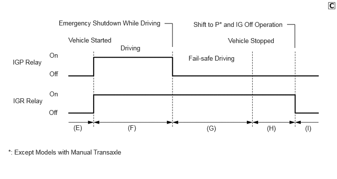
Y251596E01
6.104,0.521 6.271,0.521 6.271,0.521 6.271,1.021 true 3.5,0.5 3.667,0.5 3.667,0.5 3.667,1 true 1.458,0.771 2.75,1.01 1.292,0.24 10 false Vehicle Started 2.563,0.938 3.854,1.177 1.292,0.24 10 false Driving 4.854,0.781 6.146,1.021 1.292,0.24 10 false Vehicle Stopped 4.115,0.438 6.208,0.76 2.094,0.323 10 false Shift to P* and IG Off Operation 0.271,1.24 1.563,1.479 1.292,0.24 10 false IGP Relay 0.281,2.063 1.573,2.302 1.292,0.24 10 false IGR Relay 0.177,3.156 3.406,3.479 3.229,0.323 10 false *: Except Models with Manual Transaxle 1.052,1.094 1.583,1.396 0.531,0.302 10 false On 1.052,1.49 1.583,1.792 0.531,0.302 10 false Off 1.042,2.313 1.573,2.615 0.531,0.302 10 false Off 1.052,1.917 1.583,2.219 0.531,0.302 10 false On 1.563,2.635 2.094,2.938 0.531,0.302 10 false (E) 2.719,2.635 3.25,2.938 0.531,0.302 10 false (F) 5.677,2.646 6.208,2.948 0.531,0.302 10 false (H) 6.49,2.646 7.021,2.948 0.531,0.302 10 false (I) 1.25,0.406 3.5,0.708 2.25,0.302 10 false Emergency Shutdown While Driving 4.396,2.646 4.927,2.948 0.531,0.302 10 false (G) 4.01,1.156 5.302,1.396 1.292,0.24 10 false Fail-safe Driving


iii.

Relay Status for Timing Charts Shown Above
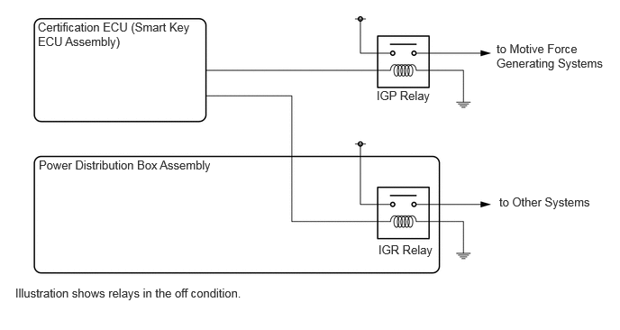
Y251597E02
5.771,2.25 7.063,2.49 1.292,0.24 10 false to Other Systems 5.74,0.479 7.031,0.865 1.292,0.385 10 false to Motive Force Generating Systems 4.354,1.021 5.646,1.26 1.292,0.24 10 false IGP Relay 4.375,2.802 5.667,3.042 1.292,0.24 10 false IGR Relay 0.177,3.302 3.406,3.625 3.229,0.323 10 false Illustration shows relays in the off condition. 0.438,0.229 2.24,0.625 1.802,0.396 10 false Certification ECU (Smart Key ECU Assembly) 0.448,1.823 2.646,2.125 2.198,0.302 10 false Power Distribution Box Assembly

Status in Timing Charts Above Relay Name Relay Status Component Carrying Coil Energization Inside Relay Power Supply Destination
(A), (D), (E), (I) IGP Relay Off - -
IGR Relay Off - -
(B), (C), (F) IGP Relay On Certification ECU (Smart Key ECU Assembly) Motive Force Generating Systems
IGR Relay On Certification ECU (Smart Key ECU Assembly) Other Systems
(G)*, (H)* IGP Relay Off - -
IGR Relay On Certification ECU (Smart Key ECU Assembly) Other Systems

HINT:

*: For vehicles without manual transaxles, even when an emergency shutdown while driving is not being performed, there are some situations when the IGP relay would be off while the IGR relay is on.