NM36W0E
_51
Engine / Hybrid System
_091266
1KR-FE ENGINE CONTROL
_0433013
SFI SYSTEM
DE
DETAILS
F
1KR-FE ENGINE CONTROL SFI SYSTEM DETAILS CRANKSHAFT POSITION SENSOR
CONSTRUCTION
a.
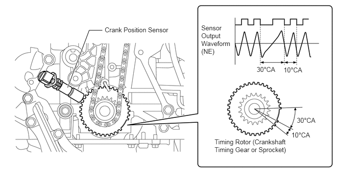
A pick-up coil type crank position sensor is used on models without stop and start system to detect crank position and crank angular velocity.
b.
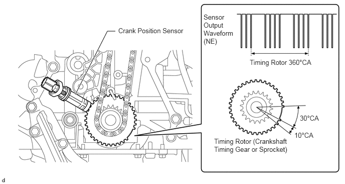
A hall type crank position sensor is used on models with stop and start system to detect accurate crank position when the engine is stopped, in order to restart the engine smoothly.
c.
The timing rotor of the crankshaft consists of 34 teeth, with 2 teeth missing. The crank position sensor outputs the crankshaft rotation signals every 10°, and the missing teeth are used to determine the top-dead-center.
Models without Stop and Start System
2.177,0.646 1.896,0.646
1.896,0.646 1.438,1.865
true
5.458,1.396 6.01,1.594
0.552,0.198
10
false
30°CA
6.313,2.479 6.865,2.677
0.552,0.198
10
false
30°CA
6.031,1.406 6.583,1.583
0.552,0.177
10
false
10°CA
6.198,2.792 6.75,2.969
0.552,0.177
10
false
10°CA
4.563,2.938 6.292,3.542
1.729,0.604
10
false
Timing Rotor (Crankshaft Timing Gear or Sprocket)
2.229,0.552 3.781,0.948
1.552,0.396
10
false
Crank Position Sensor
4.281,0.51 4.99,1.906
0.708,1.396
10
false
Sensor Output Waveform (NE)
Models with Stop and Start System
1.563,1.958 2.229,0.646
2.229,0.646 2.396,0.646
true
2.458,0.552 3.917,0.75
1.458,0.198
10
false
Crank Position Sensor
4.229,0.271 4.844,0.958
0.615,0.688
10
false
Sensor Output Waveform (NE)
5.188,1.208 6.521,1.406
1.333,0.198
10
false
Timing Rotor 360°CA
6.229,2.365 6.708,2.542
0.479,0.177
10
false
30°CA
6.115,2.719 6.594,2.896
0.479,0.177
10
false
10°CA
4.448,2.844 5.99,3.208
1.542,0.365
10
false
Timing Rotor (Crankshaft Timing Gear or Sprocket)