BRAKE SYSTEM (OTHER) BRAKE SYSTEM(for HV Model TMMF Made) DETAILS BRAKE MASTER CYLINDER
CONSTRUCTION
The electric brake booster (brake booster with master cylinder assembly) consists of a primary piston, secondary piston, boost body, and an operating rod which is directly connected to the brake pedal.
The brake pedal depression force is transmitted to the operating rod, and the booster portion which is composed of a motor and gear provides assist. The assisted brake pedal depression force pushes the primary piston and secondary piston via the boost body. In addition, the primary piston, secondary piston and boost body are provided with return springs, which allow return force to be generated even if there is no brake fluid pressure.
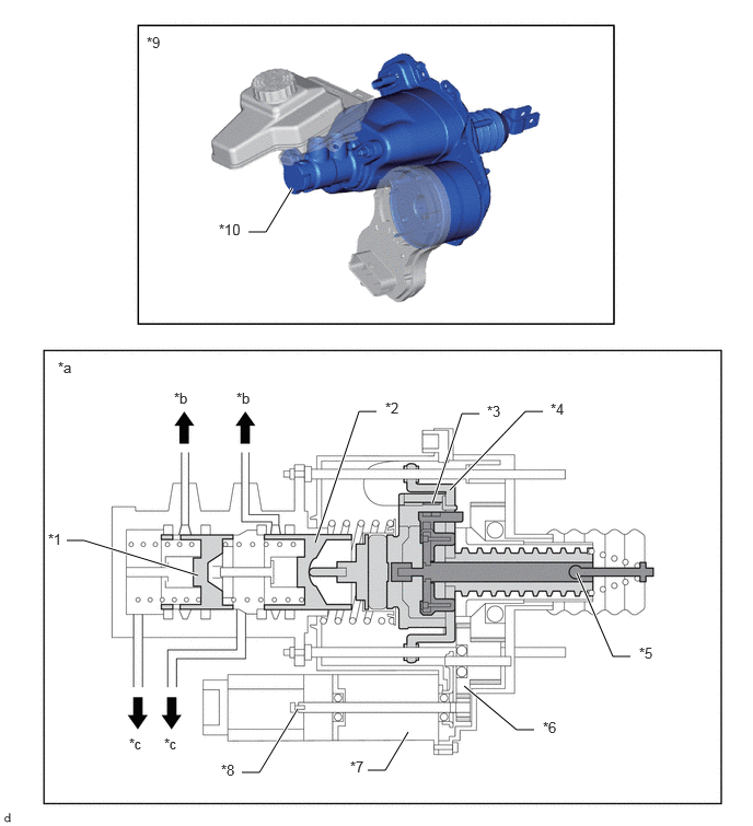
| *1 | Secondary Piston | *2 | Primary Piston |
| *3 | Relative Displacement Sensor | *4 | Boost Body |
| *5 | Operating Rod | *6 | Gear |
| *7 | Motor | *8 | Motor Rotation Angle Sensor |
| *9 | Electric Brake Booster (Brake Booster with Master Cylinder Assembly) | *10 | Brake Master Cylinder |
| *a | Brake Master Cylinder Cross Section | *b | To Brake Master Cylinder Reservoir Assembly |
| *c | To Wheel Cylinder | - | - |
OPERATION
Depressing the brake pedal causes the brake pedal to move the operating rod. The relative displacement sensor monitors the relative positions of the operating rod and boost body, and provides assist using the motor and gear so that the boost body follows the operating rod. The assist force changes according to the motor control. The assisted brake pedal depression force pushes the primary piston and secondary piston which generate brake fluid pressure inside the wheel cylinders. The motor rotation angle sensor detects the rotation angle of the motor.
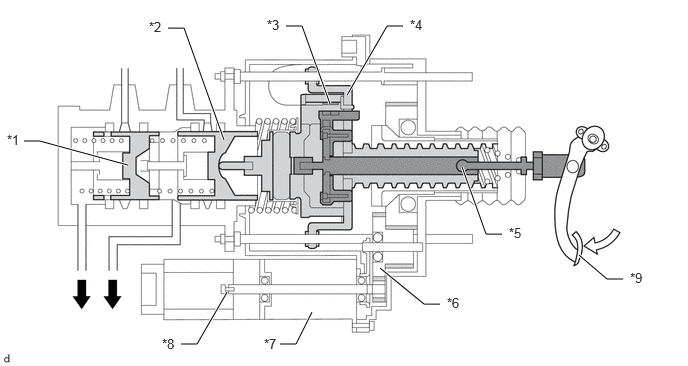
| *1 | Secondary Piston | *2 | Primary Piston |
| *3 | Relative Displacement Sensor | *4 | Boost Body |
| *5 | Operating Rod | *6 | Gear |
| *7 | Motor | *8 | Motor Rotation Angle Sensor |
| *9 | Brake Pedal | - | - |

|
To Wheel Cylinder | 
|
Brake Pedal Depression Force |