BRAKE CONTROL / DYNAMIC CONTROL SYSTEMS BRAKE CONTROL SYSTEM(for Gasoline Model) DETAILS BRAKE ACTUATOR
CONSTRUCTION (TMMF Made)
The brake actuator and skid control ECU are integrated into the brake actuator assembly to reduce size and weight.
The brake actuator controls the brake fluid pressure of each wheel cylinder and consists of the master cylinder pressure sensor, master cylinder cut solenoid valve, pressure holding solenoid valve, pressure reduction solenoid valve, pump motor, reservoir, etc.
The solenoid relay, motor relay and motor cut relay are built into the skid control ECU.
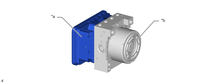
| *a | Skid Control ECU | *b | Actuator Portion |
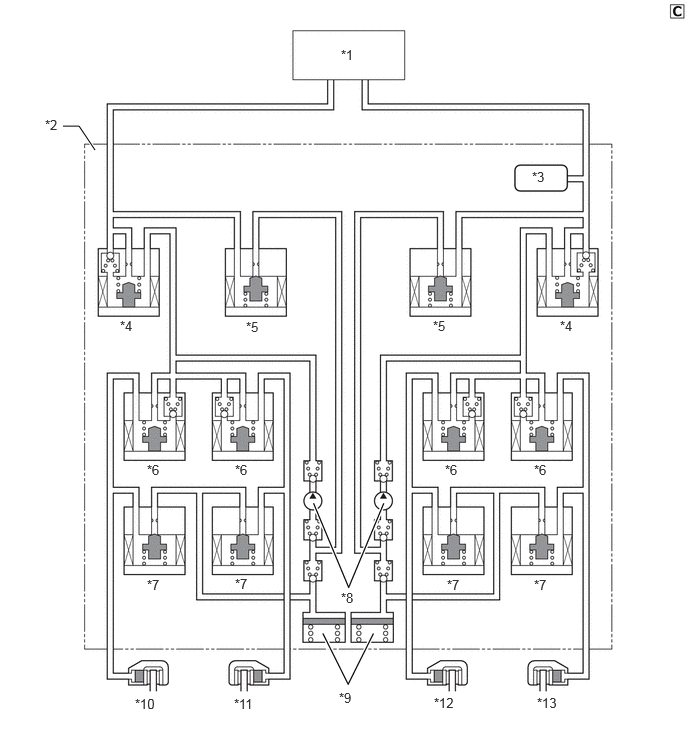
| *1 | Brake Master Cylinder Sub-assembly | *2 | Brake Actuator Assembly |
| *3 | Master Cylinder Pressure Sensor | *4 | Master Cylinder Cut Solenoid Valve |
| *5 | Reservoir Cut Solenoid Valve | *6 | Pressure Holding Solenoid Valve |
| *7 | Pressure Reduction Solenoid Valve | *8 | Pump |
| *9 | Reservoir | *10 | Front Brake Caliper RH |
| *11 | Rear Brake Caliper LH | *12 | Rear Brake Caliper RH |
| *13 | Front Brake Caliper LH | - | - |
CONSTRUCTION (TMC Made)
The brake actuator and skid control ECU are integrated into the brake actuator assembly to reduce size and weight.
The brake actuator controls the brake fluid pressure of each wheel cylinder and consists of the master cylinder pressure sensor, master cylinder cut solenoid valve, pressure holding solenoid valve, pressure reduction solenoid valve, pump motor, reservoir, etc.
The solenoid relay, motor relay and motor cut relay are built into the skid control ECU.
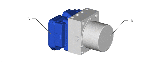
| *a | Skid Control ECU | *b | Actuator Portion |
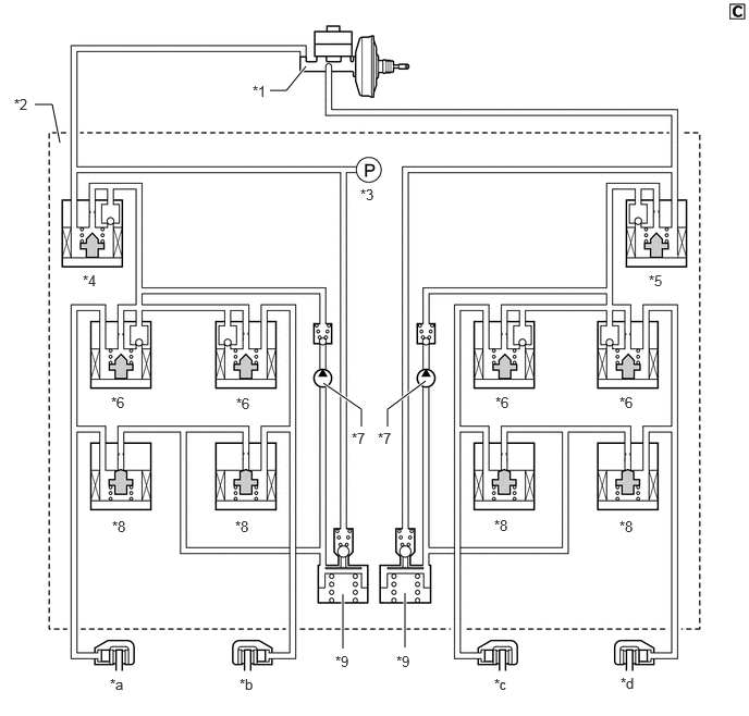
| *1 | Brake Master Cylinder Sub-assembly | *2 | Brake Actuator |
| *3 | Master Cylinder Pressure Sensor | *4 | No. 1 Master Cylinder Cut Solenoid Valve |
| *5 | No. 2 Master Cylinder Cut Solenoid Valve | *6 | Pressure Holding Solenoid Valve |
| *7 | Pump | *8 | Pressure Reduction Solenoid Valve |
| *9 | Reservoir | - | - |
| *a | Front Brake Caliper RH | *b | Rear Brake Caliper LH |
| *c | Rear Brake Caliper RH | *d | Front Brake Caliper LH |
Pressure Holding Solenoid Valve and Pressure Reduction Solenoid Valve
The skid control ECU increases, holds or decreases the brake fluid pressure of each wheel cylinder by individually turning its pressure holding solenoid valve and pressure reduction solenoid valve on or off.
Master Cylinder Cut Solenoid Valve
A linear solenoid valve is used for the master cylinder cut solenoid valve, minimizing fluctuations in the brake fluid pressure during control.
The master cylinder cut solenoid valve is turned on or off to control the brake fluid pressure from the pump to the wheel cylinder.
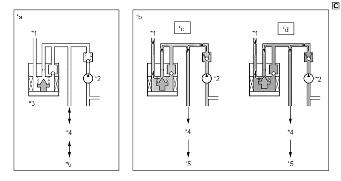
| *1 | Master Cylinder | *2 | Pump |
| *3 | Master Cylinder Cut Solenoid Valve | *4 | Pressure Holding Solenoid Valve |
| *5 | Brake Caliper | - | - |
| *a | Not Operating | *b | Operating |
| *c | Required Brake Fluid Pressure: Low | *d | Required Brake Fluid Pressure: High |
Master Cylinder Pressure Sensor
The master cylinder pressure sensor is built into the brake actuator and detects and outputs the brake fluid pressure from the master cylinder to the skid control ECU.
OPERATION (TMMF Made)
Normal Braking
During normal braking, all solenoid valves are turned off.
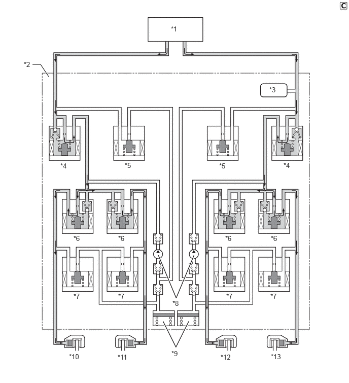
| *1 | Brake Master Cylinder Sub-assembly | *2 | Brake Actuator Assembly |
| *3 | Master Cylinder Pressure Sensor | *4 | Master Cylinder Cut Solenoid Valve |
| *5 | Reservoir Cut Solenoid Valve | *6 | Pressure Holding Solenoid Valve |
| *7 | Pressure Reduction Solenoid Valve | *8 | Pump |
| *9 | Reservoir | *10 | Front Brake Caliper RH |
| *11 | Rear Brake Caliper LH | *12 | Rear Brake Caliper RH |
| *13 | Front Brake Caliper LH | - | - |
ABS and EBD Operation
Based on the signals received from the four wheel speed sensors and yaw rate and deceleration sensor, the skid control ECU calculates the wheel rotation speed and deceleration for each wheel, in order to check for a wheel slippage condition. According to the slippage condition, the skid control ECU controls the pressure holding solenoid valves and pressure reduction solenoid valves in order to adjust the fluid pressure of the brakes for each of the wheels in the following three modes: pressure reduction, pressure holding and pressure increase modes.
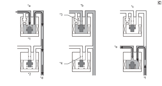
| *1 | Pressure Holding Solenoid Valve | *2 | Pressure Reduction Solenoid Valve |
| *3 | Port A | *4 | Port B |
| *a | Pressure Increase Mode | *b | Pressure Holding Mode |
| *c | Pressure Reduction Mode | *d | To Wheel Cylinder |
| *e | To Reservoir and Pump | *f | From Wheel Cylinder |
| Pressure Mode | Pressure Increase Mode | Pressure Holding Mode | Pressure Reduction Mode |
|---|---|---|---|
| Pressure Holding Solenoid Valve (Port A) | OFF (Open) | ON (Closed) | ON (Closed) |
| Pressure Reduction Solenoid Valve (Port B) | OFF (Closed) | OFF (Closed) | ON (Open) |
| Wheel Cylinder Pressure | Increases | Holds | Reduces |
Brake Assist Operation
In the event of emergency braking, the skid control ECU detects the driver's intention based on the speed of the pressure increase in the master cylinder determined by the master cylinder pressure sensor signals. If the skid control ECU judges the need for additional brake assist, pressure is generated by the pump in the brake actuator and directed to the brakes to apply a greater fluid pressure than the master cylinder. Also, in the following case, the skid control ECU provides brake assist.
In the event of a brake booster failure, the skid control ECU judges the failure using the brake pedal load sensing switch and master cylinder pressure sensor signals.
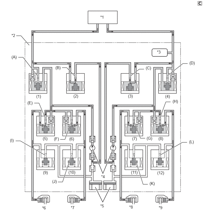
| *1 | Brake Master Cylinder Sub-assembly | *2 | Brake Actuator Assembly |
| *3 | Master Cylinder Pressure Sensor | *4 | Pump |
| *5 | Reservoir | *6 | Front Brake Caliper RH |
| *7 | Rear Brake Caliper LH | *8 | Rear Brake Caliper RH |
| *9 | Front Brake Caliper LH | - | - |
| Item | Brake Assist Not Activated | Brake Assist Activated | ||
|---|---|---|---|---|
|
*: Hydraulic pressure is controlled by continuously cycling the solenoid valves between open and closed, according to the operating conditions. |
||||
| Pump | OFF | ON | ||
| Master Cylinder Cut Solenoid Valve | (1) | Port (A) | OFF (Open) | ON* |
| (4) | Port (D) | OFF (Open) | ON* | |
| Reservoir Cut Solenoid Valve | (2) | Port (B) | OFF (Closed) | ON (Open) |
| (3) | Port (C) | OFF (Closed) | ON (Open) | |
| Pressure Holding Solenoid Valve | (5) | Port (E) | OFF (Open) | OFF (Open) |
| (6) | Port (F) | OFF (Open) | OFF (Open) | |
| (7) | Port (G) | OFF (Open) | OFF (Open) | |
| (8) | Port (H) | OFF (Open) | OFF (Open) | |
| Pressure Reduction Solenoid Valve | (9) | Port (I) | OFF (Closed) | OFF (Closed) |
| (10) | Port (J) | OFF (Closed) | OFF (Closed) | |
| (11) | Port (K) | OFF (Closed) | OFF (Closed) | |
| (12) | Port (L) | OFF (Closed) | OFF (Closed) | |
TRC Operation
The fluid pressure generated by the pump is regulated by the master cylinder cut solenoid valve to the required pressure. As a result, the wheel cylinders of the drive wheels are controlled in the following 3 modes: pressure reduction, pressure holding, and pressure increase modes to control the slippage of the drive wheels.
The TRC operation diagram shows the hydraulic circuit in the pressure increase mode when the TRC is activated.
The pressure holding solenoid valve and the pressure reduction solenoid valve are turned on/off according to the ABS with EBD operation pattern.
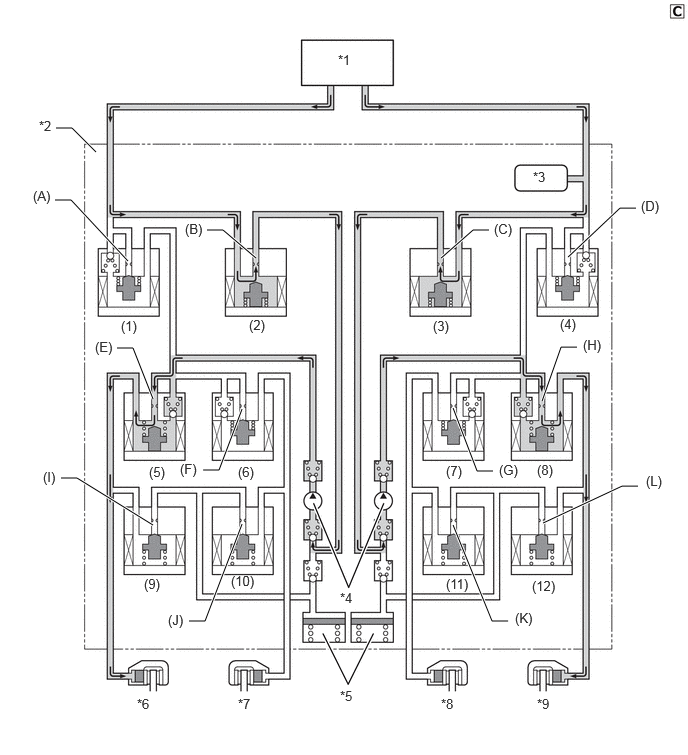
| *1 | Brake Master Cylinder Sub-assembly | *2 | Brake Actuator Assembly |
| *3 | Master Cylinder Pressure Sensor | *4 | Pump |
| *5 | Reservoir | *6 | Front Brake Caliper RH |
| *7 | Rear Brake Caliper LH | *8 | Rear Brake Caliper RH |
| *9 | Front Brake Caliper LH | - | - |
| Item | TRC Operation | ||||||
|---|---|---|---|---|---|---|---|
| Not Activated | Pressure Increase Mode | Pressure Holding Mode | Pressure Reduction Mode | ||||
|
*: Hydraulic pressure is controlled by continuously cycling the solenoid valves between open and closed, according to the operating conditions. |
|||||||
| Pump | OFF | ON | ON | ON | |||
| Master Cylinder Cut Solenoid Valve | (1) | Port (A) | OFF (Open) | ON* | ON* | ON* | |
| (4) | Port (D) | OFF (Open) | ON* | ON* | ON* | ||
| Reservoir Cut Solenoid Valve | (2) | Port (B) | OFF (Closed) | ON (Open) | ON (Open) | OFF (Closed) | |
| (3) | Port (C) | OFF (Closed) | ON (Open) | ON (Open) | OFF (Closed) | ||
| Front Brake | Pressure Holding Solenoid Valve | (5) | Port (E) | OFF (Open) | OFF (Open) | ON (Closed) | OFF (Open) |
| (8) | Port (H) | OFF (Open) | OFF (Open) | ON (Closed) | OFF (Open) | ||
| Pressure Reduction Solenoid Valve | (9) | Port (I) | OFF (Closed) | OFF (Closed) | OFF (Closed) | OFF (Closed) | |
| (12) | Port (L) | OFF (Closed) | OFF (Closed) | OFF (Closed) | OFF (Closed) | ||
| Rear Brake | Pressure Holding Solenoid Valve | (7) | Port (G) | OFF (Open) | ON (Closed) | ON (Closed) | ON (Closed) |
| (6) | Port (F) | OFF (Open) | ON (Closed) | ON (Closed) | ON (Closed) | ||
| Pressure Reduction Solenoid Valve | (11) | Port (K) | OFF (Closed) | OFF (Closed) | OFF (Closed) | OFF (Closed) | |
| (10) | Port (J) | OFF (Closed) | OFF (Closed) | OFF (Closed) | OFF (Closed) | ||
VSC Operation
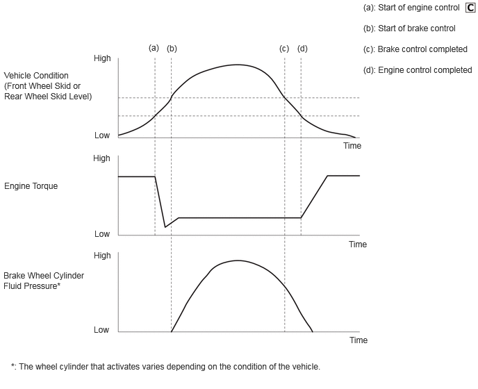
Based on the information provided by various sensors, switches and the ECM, the skid control ECU determines the vehicle's yaw moment. Then, the skid control ECU controls the fluid pressure that is generated by the pump and pump motor and applies it by way of the solenoid valves to the brake wheel cylinder of each wheel in the following three modes: pressure reduction, pressure hold and pressure increase modes. As a result, the tendency of the vehicle to experience a front wheel skid or rear wheel skid is restrained.
At this time, the skid control ECU outputs a VSC operation signal to the ECM and the combination meter. Upon receiving this signal, the ECM controls the throttle to regulate the engine output. The slip indicator light will blink in the combination meter.
Front Wheel Skid Restraining (Turning to Right)
In front wheel skid restraining control, the brake of the rear wheel of the inner side of the turn is applied. Also, depending on whether the brake is on or off and the condition of the vehicle, there are circumstances in which the brake might not be applied to a wheel even if the wheel is targeted for braking.
The diagram below shows the hydraulic circuit in the pressure increase mode, as it controls the front wheel skid condition while the vehicle makes a right turn.
In other operating modes, the pressure holding valves and the pressure reduction valves are turned on/off according to a pattern that suits the ABS and EBD operation.
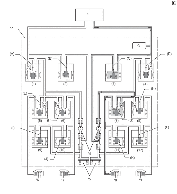
| *1 | Brake Master Cylinder Sub-assembly | *2 | Brake Actuator Assembly |
| *3 | Master Cylinder Pressure Sensor | *4 | Pump |
| *5 | Reservoir | *6 | Front Brake Caliper RH |
| *7 | Rear Brake Caliper LH | *8 | Rear Brake Caliper RH |
| *9 | Front Brake Caliper LH | - | - |
| Item | VSC Operation | ||||||
|---|---|---|---|---|---|---|---|
| Not Activated | Pressure Increase Mode | Pressure Holding Mode | Pressure Reduction Mode | ||||
|
*: Hydraulic pressure is controlled by continuously cycling the solenoid valves between open and closed, according to the operating conditions. |
|||||||
| Pump | OFF | ON | ON | ON | |||
| Master Cylinder Cut Solenoid Valve | (1) | Port (A) | OFF (Open) | OFF (Open) | OFF (Open) | OFF (Open) | |
| (4) | Port (D) | OFF (Open) | ON* | ON* | ON* | ||
| Reservoir Cut Solenoid Valve | (2) | Port (B) | OFF (Closed) | OFF (Closed) | OFF (Closed) | OFF (Closed) | |
| (3) | Port (C) | OFF (Closed) | ON (Open) | ON (Open) | OFF (Closed) | ||
| Front Brake | Pressure Holding Solenoid Valve | (5) | Port (G) | OFF (Open) | OFF (Open) | OFF (Open) | OFF (Open) |
| (8) | Port (H) | OFF (Open) | ON (Closed) | ON (Closed) | ON (Closed) | ||
| Pressure Reduction Solenoid Valve | (9) | Port (K) | OFF (Closed) | OFF (Closed) | OFF (Closed) | OFF (Closed) | |
| (12) | Port (L) | OFF (Closed) | OFF (Closed) | OFF (Closed) | OFF (Closed) | ||
| Rear Brake | Pressure Holding Solenoid Valve | (7) | Port (E) | OFF (Open) | OFF (Open) | ON (Closed) | ON (Closed) |
| (6) | Port (F) | OFF (Open) | OFF (Open) | OFF (Open) | OFF (Open) | ||
| Pressure Reduction Solenoid Valve | (11) | Port (I) | OFF (Closed) | OFF (Closed) | OFF (Closed) | ON (Open) | |
| (10) | Port (J) | OFF (Closed) | OFF (Closed) | OFF (Closed) | OFF (Closed) | ||
Rear Wheel Skid Restraining (Turning to Right)
In rear wheel skid restraining control, the brake of the front wheel of the outer side of the turn is applied. Also, depending on whether the brake is on or off and the condition of the vehicle, there are circumstances in which the brake might not be applied to a wheel even if the wheel is targeted for braking.
The diagram below shows the hydraulic circuit in the pressure increase mode, as it controls the rear wheel skid condition while the vehicle makes a right turn.
In other operating modes, the pressure holding valve and the pressure reduction valve are turned on/off according to the ABS and EBD operation pattern.
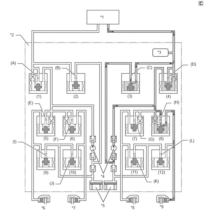
| *1 | Brake Master Cylinder Sub-assembly | *2 | Brake Actuator Assembly |
| *3 | Master Cylinder Pressure Sensor | *4 | Pump |
| *5 | Reservoir | *6 | Front Brake Caliper RH |
| *7 | Rear Brake Caliper LH | *8 | Rear Brake Caliper RH |
| *9 | Front Brake Caliper LH | - | - |
| Item | VSC Operation | ||||||
|---|---|---|---|---|---|---|---|
| Not Activated | Pressure Increase Mode | Pressure Holding Mode | Pressure Reduction Mode | ||||
|
*: Hydraulic pressure is controlled by continuously cycling the solenoid valves between open and closed, according to the operating conditions. |
|||||||
| Pump | OFF | ON | ON | ON | |||
| Master Cylinder Cut Solenoid Valve | (1) | Port (A) | OFF (Open) | OFF (Open) | OFF (Open) | OFF (Open) | |
| (4) | Port (D) | OFF (Open) | ON* | ON* | ON* | ||
| Reservoir Cut Solenoid Valve | (2) | Port (B) | OFF (Closed) | OFF (Closed) | OFF (Closed) | OFF (Closed) | |
| (3) | Port (C) | OFF (Closed) | ON (Open) | ON (Open) | OFF (Closed) | ||
| Front Brake | Pressure Holding Solenoid Valve | (5) | Port (G) | OFF (Open) | OFF (Open) | OFF (Open) | OFF (Open) |
| (8) | Port (H) | OFF (Open) | OFF (Open) | ON (Closed) | ON (Closed) | ||
| Pressure Reduction Solenoid Valve | (9) | Port (K) | OFF (Closed) | OFF (Closed) | OFF (Closed) | OFF (Closed) | |
| (12) | Port (L) | OFF (Closed) | OFF (Closed) | OFF (Closed) | ON (Open) | ||
| Rear Brake | Pressure Holding Solenoid Valve | (7) | Port (E) | OFF (Open) | ON (Closed) | ON (Closed) | ON (Closed) |
| (6) | Port (F) | OFF (Open) | OFF (Open) | OFF (Open) | OFF (Open) | ||
| Pressure Reduction Solenoid Valve | (11) | Port (I) | OFF (Closed) | OFF (Closed) | OFF (Closed) | OFF (Closed) | |
| (10) | Port (J) | OFF (Closed) | OFF (Closed) | OFF (Closed) | OFF (Closed) | ||
Active Cornering Assist (ACA) Operation
Active Cornering Assist (ACA), by way of solenoid valves, controls the fluid pressure generated by the pump and applies it to each wheel cylinder in the following 3 modes: pressure reduction, pressure holding, and pressure increase modes. As a result, understeer tendencies are controlled.
Understeer restraining control is performed by applying the brakes on the inner circle of the turn. Also, depending on whether the brakes are applied and the vehicle condition, there are circumstances in which the brake of a specific wheel may not be applied even if it was targeted for braking.
The operation of the solenoid valves under the Active Cornering Assist (ACA) is the same as the operation of the VSC front wheel skid restraining control.
Trailer Sway Control Operation
The operation of the solenoid valves under the trailer sway control is the same as the VSC operation.
Hill-start Assist Control Operation
When hill-start assist control is operating, the skid control ECU holds the brake fluid pressure.
Based on the information provided by various sensors, switches, and the ECM, the skid control ECU determines whether to activate hill-start assist control.
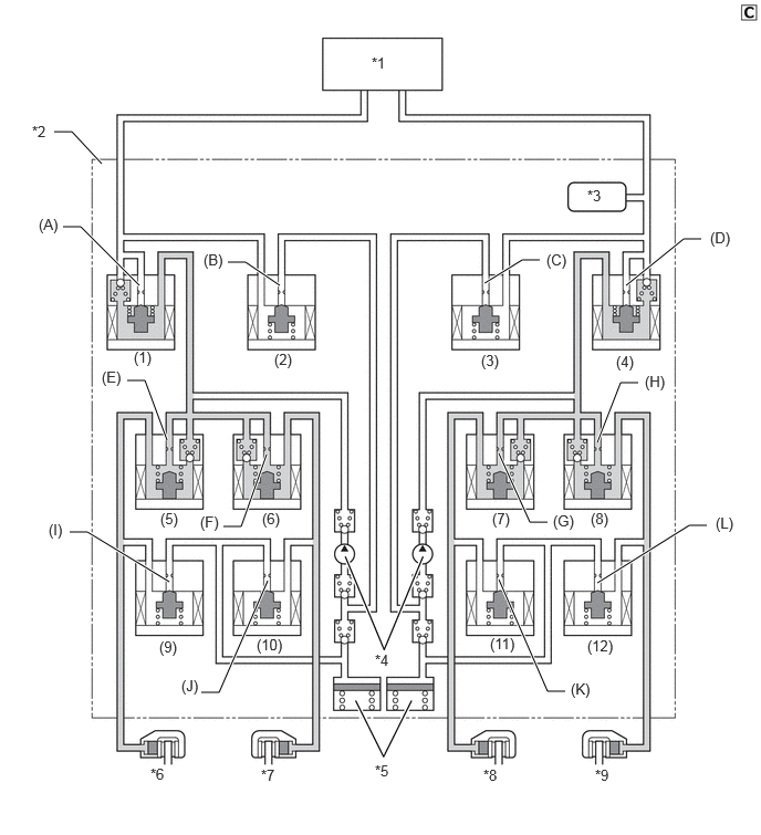
| *1 | Brake Master Cylinder Sub-assembly | *2 | Brake Actuator Assembly |
| *3 | Master Cylinder Pressure Sensor | *4 | Pump |
| *5 | Reservoir | *6 | Front Brake Caliper RH |
| *7 | Rear Brake Caliper LH | *8 | Rear Brake Caliper RH |
| *9 | Front Brake Caliper LH | - | - |
| Item | Hill-start Assist Control Operation | |||||
|---|---|---|---|---|---|---|
| Not Activated | Pressure Holding Mode | Pressure Reduction Mode | ||||
|
*: Hydraulic pressure is controlled by continuously cycling the solenoid valves between open and closed, according to the operating conditions. |
||||||
| Pump | OFF | OFF | OFF | |||
| Master Cylinder Cut Solenoid Valve | (1) | Port (A) | OFF (Open) | ON* | ON* | |
| (4) | Port (D) | OFF (Open) | ON* | ON* | ||
| Reservoir Cut Solenoid Valve | (2) | Port (B) | OFF (Closed) | OFF (Closed) | OFF (Closed) | |
| (3) | Port (C) | OFF (Closed) | OFF (Closed) | OFF (Closed) | ||
| Front Brake | Pressure Holding Solenoid Valve | (5) | Port (G) | OFF (Open) | OFF (Open) | OFF (Open) |
| (8) | Port (H) | OFF (Open) | ON (Closed) | ON (Closed) | ||
| Pressure Reduction Solenoid Valve | (9) | Port (K) | OFF (Closed) | OFF (Closed) | OFF (Closed) | |
| (12) | Port (L) | OFF (Closed) | OFF (Closed) | OFF (Closed) | ||
| Rear Brake | Pressure Holding Solenoid Valve | (7) | Port (E) | OFF (Open) | OFF (Open) | OFF (Open) |
| (6) | Port (F) | OFF (Open) | OFF (Open) | OFF (Open) | ||
| Pressure Reduction Solenoid Valve | (11) | Port (I) | OFF (Closed) | OFF (Closed) | OFF (Closed) | |
| (10) | Port (J) | OFF (Closed) | OFF (Closed) | OFF (Closed) | ||
Steering Cooperative Control Operation
The operation of the solenoid valves under the steering cooperative control is the same as the TRC or VSC operation.
Engine Output Control
During a VSC operation, the skid control ECU outputs an engine output control request signal to the ECM. Upon receiving this signal, the ECM performs throttle control to regulate the engine output.
OPERATION (TMC Made)
ABS and EBD
The ABS and EBD systems control the pump, pressure holding solenoid valve and pressure reduction valve to control the brake fluid pressure of each wheel cylinder.
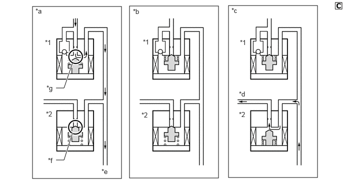
| *1 | Pressure Holding Solenoid Valve | *2 | Pressure Reduction Solenoid Valve |
| *a | Pressure Increase Mode | *b | Pressure Holding Mode |
| *c | Pressure Reduction Mode | *d | To Reservoir |
| *e | To Brake Caliper | *f | Port2 |
| *g | Port1 | - | - |
| Pressure Mode | Increase Mode | Holding Mode | Reduction Mode |
|---|---|---|---|
| Pressure Holding Solenoid Valve | OFF (Open) | ON (Closed) | ON (Closed) |
| Pressure Reduction Solenoid Valve | OFF (Closed) | OFF (Closed) | ON (Open) |
| Port1 | Open | Closed | Closed |
| Port2 | Closed | Closed | Open |
| Wheel Cylinder Pressure | Increases | Holds | Reduces |
Brake Assist
Brake assist controls each pressure holding solenoid valve and pressure reduction solenoid valve to apply brake fluid pressure higher than that of the master cylinder from the pump of the brake actuator to each wheel cylinder.
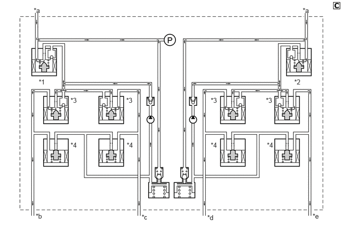
| *1 | No. 1 Master Cylinder Cut Solenoid Valve | *2 | No. 2 Master Cylinder Cut Solenoid Valve |
| *3 | Pressure Holding Solenoid Valve | *4 | Pressure Reduction Solenoid Valve |
| *a | From Brake Master Cylinder Sub-assembly | *b | To Front Brake Caliper RH |
| *c | To Rear Brake Caliper LH | *d | To Rear Brake Caliper RH |
| *e | To Front Brake Caliper LH | - | - |
| Brake Assist | Not Activated | Activated |
|---|---|---|
| No. 1 Master Cylinder Cut Solenoid Valve | OFF (Open) | ON* |
| No. 2 Master Cylinder Cut Solenoid Valve | OFF (Open) | ON* |
| Pressure Holding Solenoid Valve | OFF (Open) | OFF (Open) |
| Pressure Reduction Solenoid Valve | OFF (Closed) | OFF (Closed) |
| Wheel Cylinder Pressure | Equivalent to Master Cylinder Brake Fluid Pressure | Higher Pressure Required than Master Cylinder Brake Fluid Pressure |
- HINT:
-
*: The solenoid valve controls the brake fluid pressure by continually opening and closing the valve in accordance with the operating conditions.
TRC
TRC limits the drive force from the engine and controls each pressure holding solenoid valve and pressure reduction solenoid valve to apply more brake fluid pressure from the pump of the brake actuator to the wheel cylinder of each drive wheel to reduce slippage.
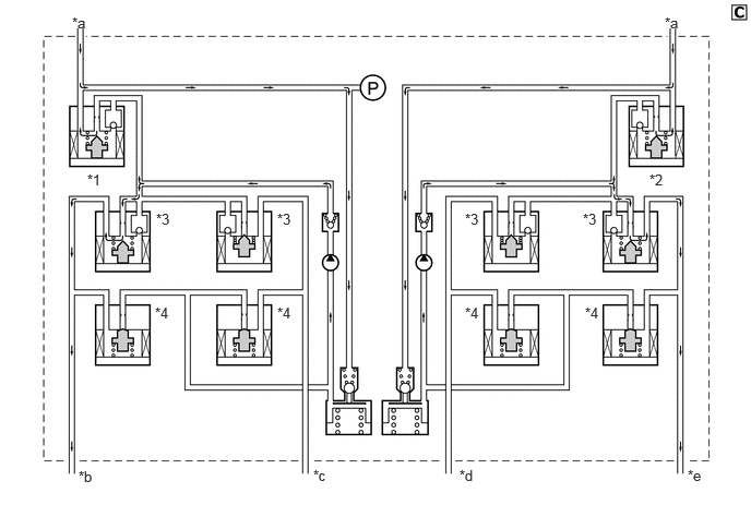
| *1 | No. 1 Master Cylinder Cut Solenoid Valve | *2 | No. 2 Master Cylinder Cut Solenoid Valve |
| *3 | Pressure Holding Solenoid Valve | *4 | Pressure Reduction Solenoid Valve |
| *a | From Brake Master Cylinder Sub-assembly | *b | To Front Brake Caliper RH |
| *c | To Rear Brake Caliper LH | *d | To Rear Brake Caliper RH |
| *e | To Front Brake Caliper LH | - | - |
| TRC | Not Activated | Activated | |||
|---|---|---|---|---|---|
| Increase Mode | Holding Mode | Reduction Mode | |||
| No. 1 Master Cylinder Cut Solenoid Valve | OFF (Open) | ON* | ON* | ON* | |
| No. 2 Master Cylinder Cut Solenoid Valve | OFF (Open) | ON* | ON* | ON* | |
| Front Wheel | Pressure Holding Solenoid Valve | OFF (Open) | OFF (Open) | ON (Closed) | ON (Closed) |
| Pressure Reduction Solenoid Valve | OFF (Closed) | OFF (Closed) | OFF (Closed) | ON (Open) | |
| Wheel Cylinder Pressure | - | Increases | Holds | Reduces | |
| Rear Wheel | Pressure Holding Solenoid Valve | OFF (Open) | ON (Closed) | ON (Closed) | ON (Closed) |
| Pressure Reduction Solenoid Valve | OFF (Closed) | OFF (Closed) | OFF (Closed) | OFF (Closed) | |
| Wheel Cylinder Pressure | - | - | - | - | |
- HINT:
-
*: The solenoid valve controls the brake fluid pressure by continually opening and closing the valve in accordance with the operating conditions.
VSC (for Oversteer)
The VSC system controls the brake fluid pressure of each wheel cylinder in order to control rear wheel skidding.
When the vehicle is oversteering while turning to the right, the VSC system controls each pressure holding solenoid valve and pressure reduction valve as shown in the illustration, in order to control rear wheel skidding.
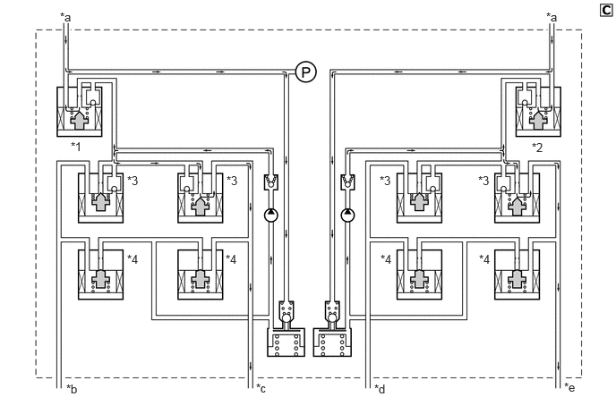
| *1 | No. 1 Master Cylinder Cut Solenoid Valve | *2 | No. 2 Master Cylinder Cut Solenoid Valve |
| *3 | Pressure Holding Solenoid Valve | *4 | Pressure Reduction Solenoid Valve |
| *a | From Brake Master Cylinder Sub-assembly | *b | To Front Brake Caliper RH |
| *c | To Rear Brake Caliper LH | *d | To Rear Brake Caliper RH |
| *e | To Front Brake Caliper LH | - | - |
| VSC | Not Activated | Activated | |||
|---|---|---|---|---|---|
| Increase Mode | Holding Mode | Reduction Mode | |||
| No. 1 Master Cylinder Cut Solenoid Valve | OFF (Open) | ON* | ON* | ON* | |
| No. 2 Master Cylinder Cut Solenoid Valve | OFF (Open) | ON* | ON* | ON* | |
| Front Wheel RH | Pressure Holding Solenoid Valve | OFF (Open) | ON (Closed) | ON (Closed) | ON (Closed) |
| Pressure Reduction Solenoid Valve | OFF (Closed) | OFF (Closed) | OFF (Closed) | OFF (Closed) | |
| Wheel Cylinder Pressure | - | - | - | - | |
| Front Wheel LH | Pressure Holding Solenoid Valve | OFF (Open) | OFF (Open) | ON (Closed) | ON (Closed) |
| Pressure Reduction Solenoid Valve | OFF (Closed) | OFF (Closed) | OFF (Closed) | ON (Open) | |
| Wheel Cylinder Pressure | - | Increases | Holds | Reduces | |
| Rear Wheel RH | Pressure Holding Solenoid Valve | OFF (Open) | ON (Closed) | ON (Closed) | ON (Closed) |
| Pressure Reduction Solenoid Valve | OFF (Closed) | OFF (Closed) | OFF (Closed) | OFF (Closed) | |
| Wheel Cylinder Pressure | - | - | - | - | |
| Rear Wheel LH | Pressure Holding Solenoid Valve | OFF (Open) | OFF (Open) | ON (Closed) | ON (Closed) |
| Pressure Reduction Solenoid Valve | OFF (Closed) | OFF (Closed) | OFF (Closed) | ON (Open) | |
| Wheel Cylinder Pressure | - | Increases | Holds | Reduces | |
- HINT:
-
*: The solenoid valve controls the brake fluid pressure by continually opening and closing the valve in accordance with the operating conditions.
VSC (for Understeer)
The VSC system controls the brake fluid pressure of each wheel cylinder in order to control front wheel skidding.
When the vehicle is understeering while turning to the right, the VSC system controls each pressure holding solenoid valve and pressure reduction valve as shown in the illustration, in order to control front wheel skidding.
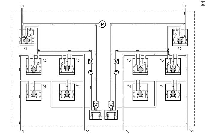
| *1 | No. 1 Master Cylinder Cut Solenoid Valve | *2 | No. 2 Master Cylinder Cut Solenoid Valve |
| *3 | Pressure Holding Solenoid Valve | *4 | Pressure Reduction Solenoid Valve |
| *a | From Brake Master Cylinder Sub-assembly | *b | To Front Brake Caliper RH |
| *c | To Rear Brake Caliper LH | *d | To Rear Brake Caliper RH |
| *e | To Front Brake Caliper LH | - | - |
| VSC | Not Activated | Activated | |||
|---|---|---|---|---|---|
| Increase Mode | Holding Mode | Reduction Mode | |||
| No. 1 Master Cylinder Cut Solenoid Valve | OFF (Open) | ON* | ON* | ON* | |
| No. 2 Master Cylinder Cut Solenoid Valve | OFF (Open) | ON* | ON* | ON* | |
| Front Wheel RH | Pressure Holding Solenoid Valve | OFF (Open) | OFF (Open) | ON (Closed) | ON (Closed) |
| Pressure Reduction Solenoid Valve | OFF (Closed) | OFF (Closed) | OFF (Closed) | ON (Open) | |
| Wheel Cylinder Pressure | - | Increases | Holds | Reduces | |
| Front Wheel LH | Pressure Holding Solenoid Valve | OFF (Open) | OFF (Open) | ON (Closed) | ON (Closed) |
| Pressure Reduction Solenoid Valve | OFF (Closed) | OFF (Closed) | OFF (Closed) | ON (Open) | |
| Wheel Cylinder Pressure | - | Increases | Holds | Reduces | |
| Rear Wheel RH | Pressure Holding Solenoid Valve | OFF (Open) | OFF (Open) | ON (Closed) | ON (Closed) |
| Pressure Reduction Solenoid Valve | OFF (Closed) | OFF (Closed) | OFF (Closed) | ON (Open) | |
| Wheel Cylinder Pressure | - | Increases | Holds | Reduces | |
| Rear Wheel LH | Pressure Holding Solenoid Valve | OFF (Open) | ON (Closed) | ON (Closed) | ON (Closed) |
| Pressure Reduction Solenoid Valve | OFF (Closed) | OFF (Closed) | OFF (Closed) | OFF (Closed) | |
| Wheel Cylinder Pressure | - | - | - | - | |
- HINT:
-
*: The solenoid valve controls the brake fluid pressure by continually opening and closing the valve in accordance with the operating conditions.
Active Cornering Assist (ACA)
Active Cornering Assist (ACA), by way of solenoid valves, controls the fluid pressure generated by the pump and applies it to each wheel cylinder in the following 3 modes: pressure reduction, pressure holding, and pressure increase modes. As a result, understeer tendencies are controlled.
Understeer restraining control is performed by applying the brakes for the wheels on the inner circle of the turn. Also, depending on whether the brakes are applied and the vehicle condition, there are circumstances in which the brake of a specific wheel may not be applied even if it was targeted for braking.
The operation of the solenoid valves under the Active Cornering Assist (ACA) is the same as the operation of the VSC understeer restraining control.
Hill-start Assist Control
Hill-start assist control temporarily maintains the brake fluid pressure of all 4 wheels to prevent the vehicle from rolling backward.
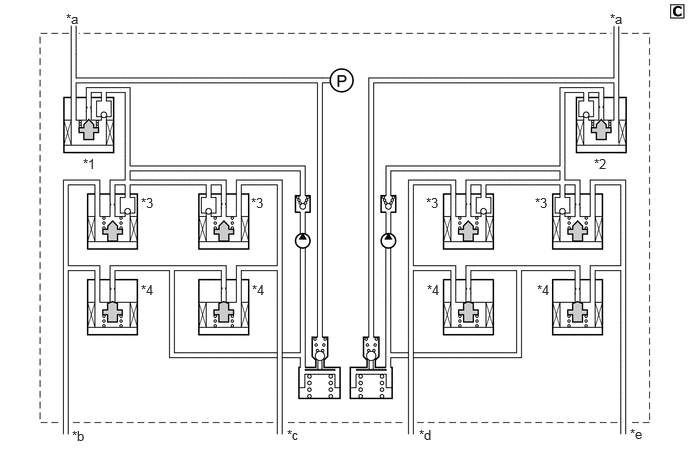
| *1 | No. 1 Master Cylinder Cut Solenoid Valve | *2 | No. 2 Master Cylinder Cut Solenoid Valve |
| *3 | Pressure Holding Solenoid Valve | *4 | Pressure Reduction Solenoid Valve |
| *a | From Brake Master Cylinder Sub-assembly | *b | To Front Brake Caliper RH |
| *c | To Rear Brake Caliper LH | *d | To Rear Brake Caliper RH |
| *e | To Front Brake Caliper LH | - | - |
| Hill-assist Control | Not Activated | Activated | ||
|---|---|---|---|---|
| Holding Mode | Reduction Mode | |||
| No. 1 Master Cylinder Cut Solenoid Valve | OFF (Open) | ON (Closed) | OFF (Open) | |
| No. 2 Master Cylinder Cut Solenoid Valve | OFF (Open) | ON (Closed) | OFF (Open) | |
| Front Wheel | Pressure Holding Solenoid Valve | OFF (Open) | OFF (Open) | OFF (Open) |
| Pressure Reduction Solenoid Valve | OFF (Closed) | OFF (Closed) | OFF (Closed) | |
| Wheel Cylinder Pressure | - | Holds | Reduces | |
| Rear Wheel | Pressure Holding Solenoid Valve | OFF (Open) | OFF (Open) | OFF (Open) |
| Pressure Reduction Solenoid Valve | OFF (Closed) | OFF (Closed) | OFF (Closed) | |
| Wheel Cylinder Pressure | - | Holds | Reduces | |
Steering Cooperative Control Operation
The operation of the solenoid valves under the steering cooperative control is the same as the TRC or VSC operation.