NM36W0E
_52
Drivetrain
_088264
EC6E MANUAL TRANSMISSION / TRANSAXLE
_0420880
MANUAL TRANSAXLE SYSTEM
DE
DETAILS
F
EC6E MANUAL TRANSMISSION / TRANSAXLE MANUAL TRANSAXLE SYSTEM DETAILS GEAR TRAIN
CONSTRUCTION
a.
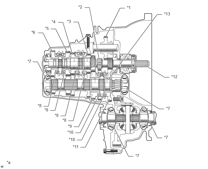
The arrangement of gears consists, for forward gear, of 2 parallel shafts which transmit power using a specific pair of gears for each shift range, and for reverse gear, a selective sliding type reverse idler gear located between the 1st and 2nd gears.
b.
Low-friction bearings are used for the output shaft and differential bearings.
c.
A triple-cone type synchronizer ring is used for 1st and 2nd gears.
d.
A single-cone type synchronizer ring is used for 3rd, 4th, 5th and 6th gears.
2.333,1.833 1.917,1
1.917,1 1.75,1
true
2.5,1.885 2.167,0.771
2.167,0.771 2,0.771
true
3.031,1.875 2.698,0.76
2.698,0.76 2.531,0.76
true
3.417,2.052 3.083,0.26
3.083,0.26 2.917,0.26
true
3.635,1.281 4.135,0.281
4.135,0.281 4.302,0.281
true
3.729,2.76 5.417,0.5
5.417,0.5 5.583,0.5
true
4.406,3.094 5.49,3.76
5.49,3.76 5.656,3.76
true
5,2.25 5.667,2.667
5.667,2.667 5.833,2.667
true
5.594,4.76 5.427,4.76
5.427,4.76 5.094,4.094
true
4.594,5.396 4.427,5.396
4.427,5.396 3.927,4.396
true
2.771,5.083 2.938,5.083
2.938,5.083 3.771,3.417
true
2.594,4.583 2.76,4.583
2.76,4.583 3.427,3.25
true
2.646,4.833 2.813,4.833
2.813,4.833 3.604,3.25
true
2.542,4.375 2.708,4.375
2.708,4.375 3.208,3.375
true
2.354,4.167 2.521,4.167
2.521,4.167 2.938,2.5
true
1.542,2.635 1.292,2.135
1.292,2.135 1.125,2.135
true
1.5,3.667 1.667,3.667
1.667,3.667 1.917,2.479
true
1.729,3.813 1.896,3.813
1.896,3.813 2.229,2.479
true
2.083,4 2.25,4
2.25,4 2.625,2.5
true
1.813,1.802 1.479,1.135
1.479,1.135 1.313,1.135
true
4.375,0.177 4.688,0.333
0.313,0.156
10
false
*1
2.698,0.156 3.01,0.313
0.313,0.156
10
false
*2
2.313,0.656 2.625,0.813
0.313,0.156
10
false
*3
1.781,0.667 2.094,0.823
0.313,0.156
10
false
*4
1.552,0.896 1.865,1.052
0.313,0.156
10
false
*5
1.083,1.031 1.396,1.188
0.313,0.156
10
false
*6
0.948,2.031 1.26,2.188
0.313,0.156
10
false
*7
1.302,3.563 1.667,3.75
0.365,0.188
10
false
*8
1.531,3.708 1.896,3.896
0.365,0.188
10
false
*8
1.885,3.896 2.25,4.083
0.365,0.188
10
false
*8
2.156,4.063 2.521,4.25
0.365,0.188
10
false
*8
2.344,4.271 2.656,4.427
0.313,0.156
10
false
*9
2.323,4.479 2.635,4.635
0.313,0.156
10
false
*10
2.375,4.729 2.688,4.885
0.313,0.156
10
false
*10
2.51,4.979 2.823,5.135
0.313,0.156
10
false
*11
4.667,5.292 4.979,5.448
0.313,0.156
10
false
*7
5.656,4.656 5.969,4.813
0.313,0.156
10
false
*7
5.729,3.656 6.042,3.813
0.313,0.156
10
false
*7
5.906,2.563 6.219,2.719
0.313,0.156
10
false
*12
5.656,0.396 5.969,0.552
0.313,0.156
10
false
*13
0.229,5.521 0.542,5.677
0.313,0.156
10
false
*a
| *1 | Reverse Idler Gear Sub-assembly | *2 | Reverse Gear |
| *3 | 3rd Gear | *4 | 4th Gear |
| *5 | 5th Gear | *6 | 6th Gear Sub-assembly |
| *7 | Low-friction Bearing | *8 | Synchronizer Ring (Single-cone) |
| *9 | 2nd Gear | *10 | Synchronizer Ring (Triple-cone) |
| *11 | 1st Gear | *12 | Input Shaft |
| *13 | Output Shaft | - | - |
| *a | The illustrations shown are examples only. | - | - |
OPERATION
a.
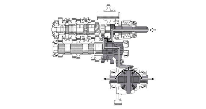
Gear Train Operation (1st)
b.
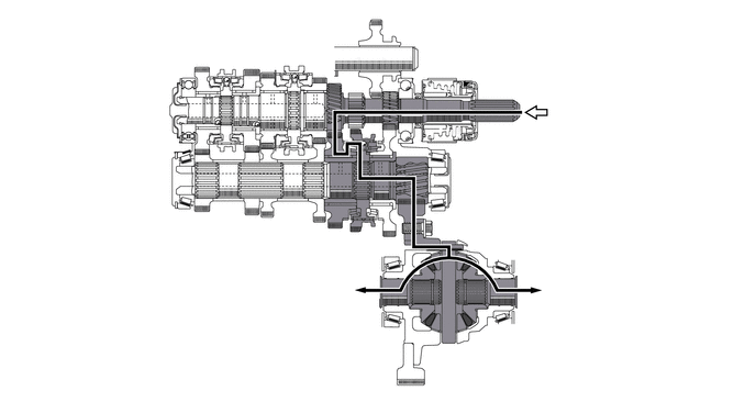
Gear Train Operation (2nd)
c.
Gear Train Operation (3rd)
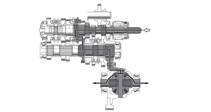
d.
Gear Train Operation (4th)
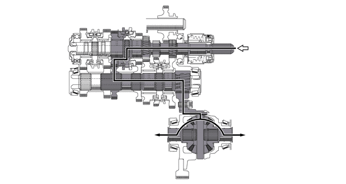
e.
Gear Train Operation (5th)
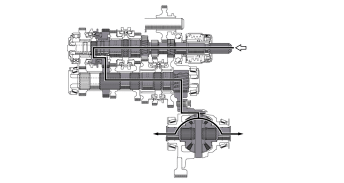
f.
Gear Train Operation (6th)
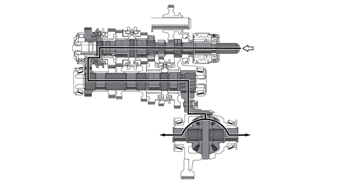
g.
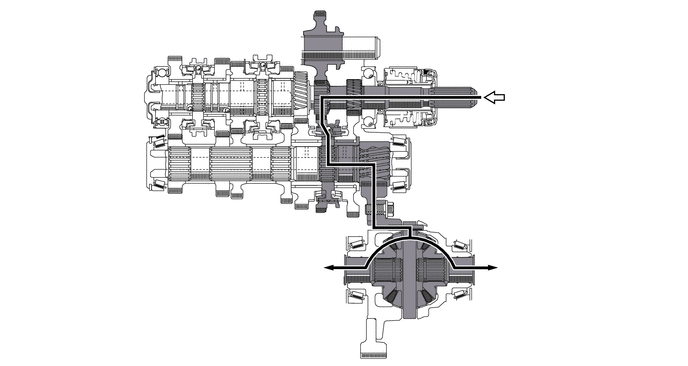
Gear Train Operation (Reverse)