Home › Drivetrain › EC6E (MANUAL TRANSMISSION / TRANSAXLE) › MANUAL TRANSAXLE SYSTEM › from 2020.07
NM36W0E _52 Drivetrain _088264 EC6E MANUAL TRANSMISSION / TRANSAXLE _0420880 MANUAL TRANSAXLE SYSTEM CO CONTROL F

EC6E MANUAL TRANSMISSION / TRANSAXLE  MANUAL TRANSAXLE SYSTEM  CONTROL  GEAR SHIFT INDICATOR SYSTEM  


FUNCTION


a.

Gear Shift Indicator (Models with Gear Shift Indicator System)

i.

In the Gear Shift Indicator, the ECM calculates to determine a gear position for good environmental performance from vehicle conditions, and requests the combination meter assembly to indicate "upshifting/downshifting". Then, the Gear Shift Indicator in the combination meter assembly shows the driver to shift recommendation.


ii.

The ECM determines the actual gear position based on the signals from the speed sensor and crank position sensor, and the target gear position based on the signals from the accelerator pedal sensor assembly and speed sensor.


iii.

By driving in accordance with the shift change recommendations that are indicated by the Gear Shift Indicator, the driver can enhance environmental performance, improving fuel economy and reducing exhaust gas output with in limits of engine performance.
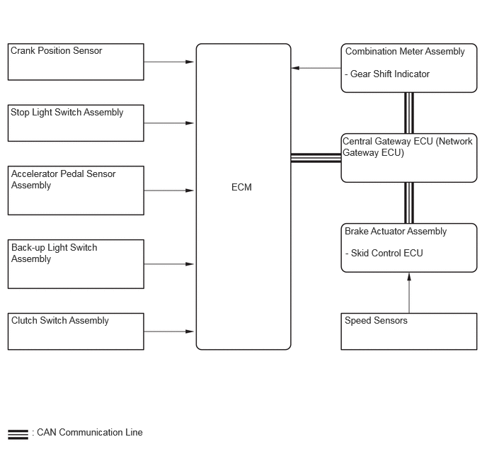
X147228E01
0.156,0.656 1.719,1.083 1.563,0.427 10 false Crank Position Sensor 0.156,1.563 1.938,1.99 1.781,0.427 10 false Stop Light Switch Assembly 0.167,2.469 1.76,2.896 1.594,0.427 10 false Accelerator Pedal Sensor Assembly 0.167,3.552 1.51,3.99 1.344,0.438 10 false Back-up Light Switch Assembly 0.167,4.625 1.729,5.052 1.563,0.427 10 false Clutch Switch Assembly 5.083,0.667 6.927,1.073 1.844,0.406 10 false Combination Meter Assembly 5.042,1.99 6.979,2.479 1.938,0.49 10 false Central Gateway ECU (Network Gateway ECU) 5.073,3.313 6.74,3.708 1.667,0.396 10 false Brake Actuator Assembly 5.073,4.625 6.635,5.052 1.563,0.427 10 false Speed Sensors 3.406,2.667 4.073,3.021 0.667,0.354 10 false ECM 0.469,6.271 3.01,6.573 2.542,0.302 10 false : CAN Communication Line 5.073,1 6.917,1.406 1.844,0.406 10 false - Gear Shift Indicator 5.083,3.635 6.75,4.031 1.667,0.396 10 false - Skid Control ECU

Control of Gear Shift Indicator
Control Outline
System Start Checks the bulb of the indicator lights from the time the ignition switch is turned ON until the engine is started.
Shifting Recommendation Control Calculates an environmentally favorable shift position based on the driving conditions of the vehicle, and gives shifting recommendation.
Shift Control in Uphill Traveling Prevents unnecessary shifting instruction by estimating the gradient of the road based on the driving conditions. Provides shift position instructions that enable the vehicle to attain the proper drive force.
Delta Throttle Accelerate Control Determines a deceleration request when the driver releases the accelerator pedal suddenly. Thus, it will not provide a shift-up instruction. However, it will provide a shift-up recommendation to protect the engine if the engine speed is high.


iv.

The Gear Shift Indicator will not effect control while the vehicle is being driven in reverse.


v.

The Gear Shift Indicator will not effect control while the vehicle is stopped or the clutch is not being engaged while shifting.


vi.

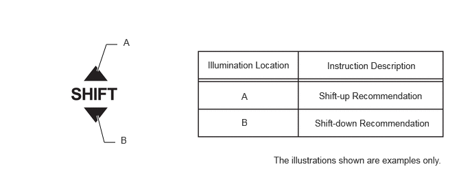
Upon receiving a shift instruction request from the ECM, the combination meter assembly will illuminate the indicator light.
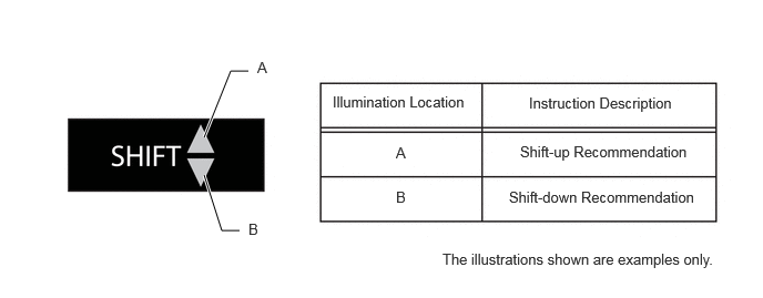
Models with Digital type combination meter assembly
X147229E01
1.917,1.292 2.167,0.667 2.167,0.667 2.333,0.667 true 1.917,1.646 2.083,2.167 2.083,2.167 2.25,2.167 true 2.417,0.552 2.573,0.729 0.156,0.177 10 false A 2.333,2.073 2.49,2.25 0.156,0.177 10 false B 3.125,0.875 4.396,1.063 1.271,0.188 10 false Illumination Location 4.969,0.885 6.375,1.094 1.406,0.208 10 false Instruction Description 3.719,1.354 3.875,1.531 0.156,0.177 10 false A 3.719,1.771 3.875,1.948 0.156,0.177 10 false B 4.885,1.344 6.5,1.552 1.615,0.208 10 false Shift-up Recommendation 4.781,1.771 6.573,1.979 1.792,0.208 10 false Shift-down Recommendation 4.156,2.354 7.156,2.583 3,0.229 10 false The illustrations shown are examples only.

Models with Analog type combination meter assembly
X147230E01
1.479,1.083 1.615,0.677 1.615,0.677 1.781,0.677 true 1.479,1.76 1.583,2.167 1.583,2.167 1.75,2.167 true 1.875,0.563 2.031,0.74 0.156,0.177 10 false A 1.833,2.052 1.99,2.229 0.156,0.177 10 false B 3.156,0.906 4.427,1.094 1.271,0.188 10 false Illumination Location 4.969,0.917 6.375,1.125 1.406,0.208 10 false Instruction Description 3.667,1.385 3.823,1.563 0.156,0.177 10 false A 3.667,1.781 3.823,1.958 0.156,0.177 10 false B 4.844,1.375 6.458,1.583 1.615,0.208 10 false Shift-up Recommendation 4.781,1.792 6.573,2 1.792,0.208 10 false Shift-down Recommendation 4.156,2.354 7.156,2.583 3,0.229 10 false The illustrations shown are examples only.