Home › Engine / Hybrid System › G16E-GTS (FUEL) › FUEL SYSTEM › from 2020.09
NM36W0E _51 Engine / Hybrid System _095168 G16E-GTS FUEL _0447254 FUEL SYSTEM DE DETAILS F

G16E-GTS FUEL  FUEL SYSTEM  DETAILS  FUEL PUMP (FOR HIGH PRESSURE)  


CONSTRUCTION


a.

A high-efficiency single plunger type is used to reduce driving torque.


b.

Consists of an electromagnetic spill valve that adjusts the amount of discharged high pressure fuel, a plunger that is operated by the exhaust camshaft to pressurize the fuel, a check valve that mechanically opens and closes the path to the fuel delivery pipe and relief valve that leaks fuel at a high pressure fuel system malfunction.


c.

A roller lifter (fuel pump lifter assembly) is used to operate the plunger, supporting higher output and higher fuel pressure.


d.

Installed to the fuel pump lifter housing, and is operated by a cam installed to the exhaust camshaft.


e.

The high pressure fuel pressure is variably controlled between 2.4 and 22 MPa according to driving conditions to reduce friction losses.


f.

A metal taper seal is used for the fuel pipe (for high pressure) fastener.
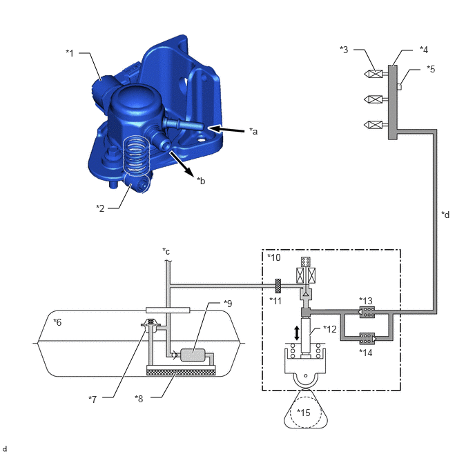
W146052C01
1.188,0.802 1.354,0.802 1.354,0.802 1.521,1.219 true 2.906,5.323 3.146,4.573 3.146,4.573 3.323,4.573 true 2.271,6 2.438,6 2.438,6 2.656,5.615 true 6.031,1.292 6.177,1.052 6.177,1.052 6.344,1.052 true 4.667,5.063 4.75,4.958 4.75,4.958 4.833,4.958 true 1.625,3.146 1.792,3.146 1.792,3.146 1.979,2.771 true 5.917,1 6.063,0.76 6.063,0.76 6.229,0.76 true 1.542,6 1.708,6 1.708,6 2.198,4.979 true 5.333,0.75 5.5,0.75 5.5,0.75 5.667,1.083 true 1.448,3.063 1.76,3.219 0.313,0.156 10 false *2 5.125,0.667 5.438,0.823 0.313,0.156 10 false *3 0.802,4.781 1.115,4.938 0.313,0.156 10 false *6 2.031,5.938 2.344,6.094 0.313,0.156 10 false *8 6.333,0.667 6.646,0.823 0.313,0.156 10 false *4 1.333,5.948 1.646,6.104 0.313,0.156 10 false *7 4.063,4.458 4.375,4.615 0.313,0.156 10 false *11 3.375,4.5 3.688,4.656 0.313,0.156 10 false *9 4.031,3.802 4.5,3.958 0.469,0.156 10 false *10 4.875,4.885 5.344,5.042 0.469,0.156 10 false *12 5.417,4.458 5.885,4.615 0.469,0.156 10 false *13 5.417,5.24 5.885,5.396 0.469,0.156 10 false *14 4.479,6.146 4.948,6.302 0.469,0.156 10 false *15 3.76,1.896 4.073,2.052 0.313,0.156 10 false *a 2.969,2.646 3.281,2.802 0.313,0.156 10 false *b 6.656,3.156 6.969,3.313 0.313,0.156 10 false *d 0.99,0.719 1.302,0.875 0.313,0.156 10 false *1 6.438,0.958 6.75,1.115 0.313,0.156 10 false *5 2.448,3.708 2.917,3.865 0.469,0.156 10 false *c
*1 Spill Control Valve *2 Roller Lifter (Fuel Pump Lifter Assembly)
*3 Direct Fuel Injector Assembly *4 Fuel Delivery Pipe Sub-assembly (for Direct Injection)
*5 Fuel Pressure Sensor (for High Pressure) *6 Fuel Tank Sub-assembly
*7 Fuel Main Valve Assembly *8 Fuel Filter
*9 Fuel Pump (for Low Pressure) *10 Fuel Pump Assembly (for High Pressure)
*11 Fuel SUS Filter *12 Plunger
*13 Check Valve *14 Fuel Relief Valve
*15 Exhaust Camshaft Sub-assembly (Cam to Drive Fuel Pump Assembly) - -
*a Low-pressure Fuel (from Fuel Tank Sub-assembly) *b High-pressure Fuel (to Fuel Delivery Pipe Sub-assembly (for Direct Injection))
*c To Fuel Delivery Pipe (for Port Injection) *d High-pressure Fuel Pipe


OPERATION


a.

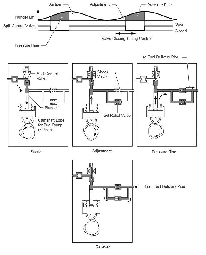
During the exhaust camshaft portion of the pump cycle, the spill control valve is opened, and the pump plunger (piston) is moved downward by spring force. This allows fuel to be drawn into the cylinder of the pump. If the spill control valve has not been closed yet, when the cam forces the plunger to move upward, the fuel in the pump cylinder (this fuel is not pressurized) will be pushed back to the pump inlet (fuel tank side).


b.

In order to close the spill control valve as the piston is moving upward, the ECM sends a signal to the valve. When the spill control valve is closed and the plunger is moving upward, the pressure in the pump cylinder will rise. As this pressure rises above 60 kPa (or the pressure of the delivery pipe, whichever is higher), the fuel will begin to flow to the fuel delivery pipe (for high pressure side). The ECM calculates the target fuel pressure based on driving conditions. The ECM controls the pressure by operating the spill control valve. The timing and duration of the spill control valve closing are varied to cause the pump pressure to meet the target pressure.


c.

If the fuel pressure in the high-pressure fuel pipes is abnormally high, the relief valve discharges some of fuel in order to limit the pressure.
W130109E09
1.417,1.583 1.594,1.583 1.594,1.583 2.167,0.583 true 4.771,0.552 4.917,0.167 4.917,0.167 5.063,0.167 true 6.333,2 6.5,2 6.5,2 6.583,3.031 true 1.219,2.552 1.052,2.552 true 1.5,3.75 1.417,3.75 1.417,3.75 0.979,3.323 true 1.26,4.177 1.177,4.177 1.177,4.177 1.031,4.438 true 3.833,2.5 4,2.5 4,2.5 4.167,3.083 true 4.083,3.917 4.083,3.583 true 3.896,0.167 4.042,0.167 4.042,0.167 4.313,0.656 true 2.208,0.167 2.375,0.167 2.375,0.167 2.542,0.5 true 0.51,0.51 1.271,0.75 0.76,0.24 10 false Plunger Lift 0.115,0.813 1.26,1.083 1.146,0.271 10 false Spill Control Valve 0.51,1.49 1.479,1.708 0.969,0.219 10 false Pressure Rise 1.677,0.063 2.177,0.281 0.5,0.219 10 false Suction 5.125,0.083 6.042,0.26 0.917,0.177 10 false Pressure Rise 3.542,1.25 5.333,1.479 1.792,0.229 10 false Valve Closing Timing Control 6.083,0.76 6.448,0.99 0.365,0.229 10 false Open 6.083,0.99 6.573,1.208 0.49,0.219 10 false Closed 4.979,1.896 6.5,2.167 1.521,0.271 10 false to Fuel Delivery Pipe 1.281,2.479 2.135,2.854 0.854,0.375 10 false Spill Control Valve 1.552,3.667 2.042,3.917 0.49,0.25 10 false Plunger 1.323,4.094 2.281,4.865 0.958,0.771 10 false Camshaft Lobe for Fuel Pump (3 Peaks) 3.385,2.417 3.885,2.844 0.5,0.427 10 false Check Valve 3.531,3.927 4.563,4.167 1.031,0.24 10 false Fuel Relief Valve 1.063,5.198 1.615,5.427 0.552,0.229 10 false Suction 3.208,5.167 4.031,5.417 0.823,0.25 10 false Adjustment 5.281,5.198 6.281,5.375 1,0.177 10 false Pressure Rise 5.031,6.406 7.115,6.844 2.083,0.438 10 false from Fuel Delivery Pipe 3.323,8.51 3.927,8.76 0.604,0.25 10 false Relieved 3.135,0.063 3.927,0.292 0.792,0.229 10 false Adjustment