NM36W0E
_51
Engine / Hybrid System
_095168
G16E-GTS FUEL
_0447254
FUEL SYSTEM
DE
DETAILS
F
G16E-GTS FUEL FUEL SYSTEM DETAILS FUEL SENDER GAGE
CONSTRUCTION
a.
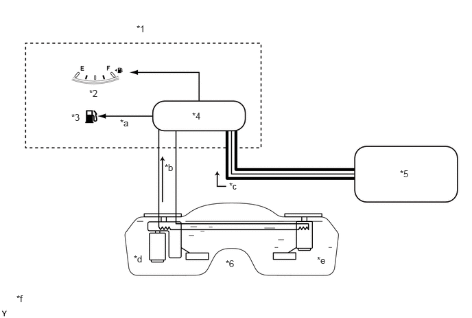
The fuel sender gauge assemblies are arranged in series in chamber A and chamber B in order to inform the driver of the accurate fuel volume remaining in the saddle shaped fuel tank. The fuel sender gauge assemblies send information of the fuel volume remaining in each chamber to the combination meter assembly.
b.
The ECM sends SFI control information to the meter ECU. The meter ECU calculates the remaining fuel volume based on the signals from the 2 fuel sender gauge assemblies and the ECM and drives the fuel gauge.
2.073,0.354 2.385,0.51
0.313,0.156
10
false
*1
1.354,1.333 1.667,1.49
0.313,0.156
10
false
*2
1.083,1.698 1.396,1.854
0.313,0.156
10
false
*3
2.917,1.677 3.229,1.833
0.313,0.156
10
false
*4
6.073,2.552 6.385,2.708
0.313,0.156
10
false
*5
3.427,3.917 3.74,4.073
0.313,0.156
10
false
*6
1.823,1.781 2.135,1.938
0.313,0.156
10
false
*a
2.5,2.458 2.813,2.615
0.313,0.156
10
false
*b
3.479,2.74 3.792,2.896
0.313,0.156
10
false
*c
2.031,3.844 2.344,4
0.313,0.156
10
false
*d
4.813,3.865 5.125,4.021
0.313,0.156
10
false
*e
0.25,4.448 0.563,4.604
0.313,0.156
10
false
*f
| *1 | Combination Meter Assembly | *2 | Fuel Meter |
| *3 | Low Fuel Warning Light | *4 | Meter ECU |
| *5 | ECM | *6 | Fuel Tank Sub-assembly |
| *a | Fuel Meter Drive Signal | *b | Fuel Volume Information Signal |
| *c | Fuel Injection Information Signal | *d | Chamber A |
| *e | Chamber B | *f | The illustrations shown are examples only. |

|
CAN Communication Line | - | - |