G16E-GTS INTAKE / EXHAUST INTAKE SYSTEM DETAILS AIR CLEANER
CONSTRUCTION
An air cleaner assembly (for dual intake system) with air intake control valve has been adopted, which switches between different air intake pathways according to driving conditions.
Aluminum tape (No. 1 molding tape) is applied to the air cleaner cap sub-assembly, which improves its electrical condition (grounding effect), thereby increasing the detection precision of the intake mass air flow meter sub-assembly, helping to realize linear responsiveness with regard to the accelerator pedal opening angle.
The fine fiber sound absorbing material, which is also utilized as an air guide, is positioned in the air cleaner assembly to reduce intake pressure loss and high-frequency engine noise, improving the balance of the engine sound.
A paper type air cleaner filter element sub-assembly is used. Additionally, a fine fiber layer has been added to the filter surface, increasing its filtering performance.
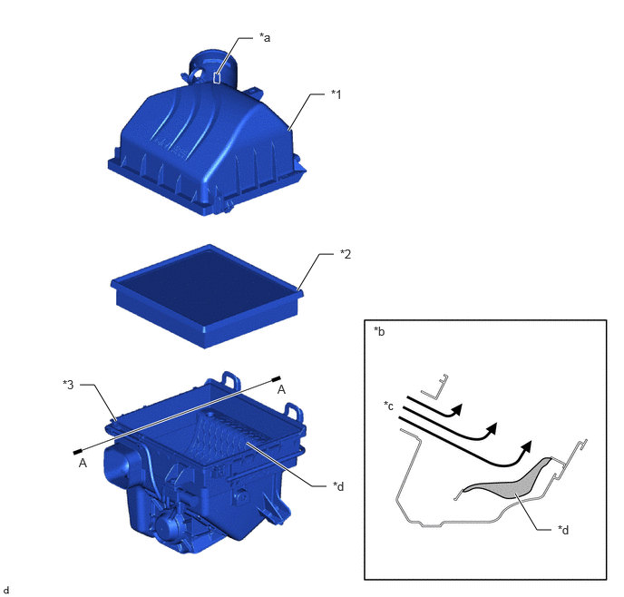
| *1 | Air Cleaner Cap Sub-assembly | *2 | Air Cleaner Filter Element Sub-assembly |
| *3 | Air Cleaner Case Sub-assembly | - | - |
| *a | Aluminum Tape (No. 1 Molding Tape) | *b | A-A Cross Section |
| *c | Intake Air | *d | Fine Fiber Sound Absorbing Material |
OPERATION
Dual Intake System
An air intake control valve has been provided on the air cleaner case sub-assembly.
Based on the signals from the ECM, the vacuum switching valve assembly (for air intake control valve) drives the actuator to open and close the air intake control valve.
At low engine speeds, only normal air intake via the No. 1 air cleaner inlet is performed, while at high engine speeds, in addition to the normal air intake the air intake control valve opens and augments the amount of intake air sent to the engine, thereby realizing higher levels of engine output performance.
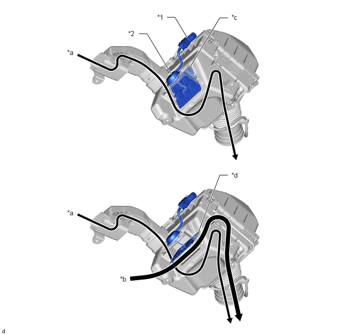
| *1 | Vacuum Switching Valve Assembly (for Air Intake Control Valve) | *2 | Actuator |
| *a | Normal Air Intake | *b | Augmented Air Intake |
| *c | Air Intake Control Valve: Closed | *d | Air Intake Control Valve: Open |