G16E-GTS ENGINE CONTROL SFI SYSTEM DETAILS CRANKSHAFT POSITION SENSOR
CONSTRUCTION
A Magnetic Resistance Element (MRE) type crank position sensor is used to detect the engine speed and crankshaft angle.
The No. 1 crankshaft position sensor plate (timing rotor) of the crankshaft consists of 34 teeth with 2 teeth missing. The crank position sensor outputs a crankshaft rotation signal every 10°, and the change of the signal due to the missing teeth is used to determine top-dead-center.
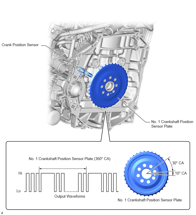
An MRE type crank position sensor consists of an MRE, a magnet and a sensor. The direction of the magnetic field changes due to the profile (protruding and non-protruding portions) of the No. 1 crankshaft position sensor plate, which passes by the sensor. As a result, the resistance of the MRE changes, and the output voltage to the ECM changes to high or low. The ECM detects the crankshaft position based on this output voltage.