Home › Engine / Hybrid System › G16E-GTS (ENGINE CONTROL) › SFI SYSTEM › from 2020.09
NM36W0E _51 Engine / Hybrid System _095207 G16E-GTS ENGINE CONTROL _0447319 SFI SYSTEM CO CONTROL F

G16E-GTS ENGINE CONTROL  SFI SYSTEM  CONTROL  TURBOCHARGER CONTROL  


FUNCTION


a.

For the turbocharger control, wastegate valve control which controls the turbo pressure and air bypass valve control which prevents the surge phenomenon* are used.

HINT:

*: Surge phenomenon: This phenomenon is when the intake airflow reverses. As a result, an abnormal noise is easily generated during deceleration.


i.

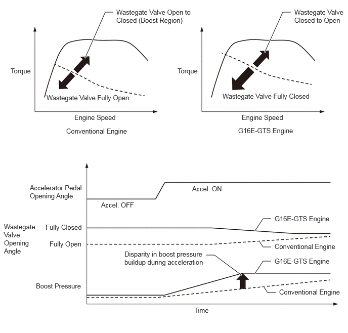
The ECM cooperatively controls the throttle valve, Dual VVT-i and wastegate valve to achieve a driving condition with optimal fuel efficiency during normal driving. Also, the ECM controls each actuator in accordance with the driver's intentions during acceleration to achieve a high torque response.


b.

Wastegate Valve Control

i.

During Engine Start

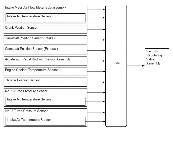
The ECM controls the vacuum regulating valve assembly to control the vacuum from the vacuum pump assembly to the actuator and open the wastegate valve. As a result, high temperature exhaust gases are supplied for the catalyst and warm-up time has been reduced.


ii.

During Light Loads and Acceleration

The ECM controls the vacuum regulating valve assembly to control the vacuum from the vacuum pump assembly to the actuator and close the wastegate valve. As a result, engine torque increase and response during acceleration have been achieved.


iii.

During High Loads

The ECM controls the vacuum regulating valve assembly to control the vacuum from the vacuum pump assembly to the actuator, opening the wastegate valve and decreasing the exhaust manifold pressure. As a result, the engine is protected.
W146006E01
1.75,1.198 2.167,0.25 2.167,0.25 2.333,0.25 true 5.448,1.083 5.823,0.25 5.823,0.25 5.99,0.25 true 5.25,5.625 5.417,5.375 5.417,5.375 5.583,5.375 true 4.979,5.667 4.417,5.25 4.417,5.25 4.25,5.25 true 5.583,5.083 5.417,5.083 5.417,5.083 5.333,4.958 true 5.25,4.75 5.417,4.5 5.417,4.5 5.583,4.5 true 5.677,6.021 5.51,6.021 5.51,6.021 5.427,5.896 true 2.396,0.167 4,0.625 1.604,0.458 10 false Wastegate Valve Open to Closed (Boost Region) 6.063,0.167 7.135,0.583 1.073,0.417 10 false Wastegate Valve Closed to Open 3.656,1.375 4.115,1.573 0.458,0.198 10 false Torque 0.219,1.375 0.677,1.573 0.458,0.198 10 false Torque 4.583,1.896 6.542,2.188 1.958,0.292 10 false Wastegate Valve Fully Closed 0.958,1.927 3.083,2.208 2.125,0.281 10 false Wastegate Valve Fully Open 4.906,2.604 6.573,2.854 1.667,0.25 10 false G16E-GTS Engine 1.531,2.333 2.781,2.583 1.25,0.25 10 false Engine Speed 4.979,2.333 5.979,2.583 1,0.25 10 false Engine Speed 1.365,2.615 3.031,2.865 1.667,0.25 10 false Conventional Engine 0.615,3.781 1.75,4.219 1.135,0.438 10 false Accelerator Pedal Opening Angle 3.958,3.802 5.625,4.052 1.667,0.25 10 false Accel. ON 2.083,4.135 3.75,4.385 1.667,0.25 10 false Accel. OFF 0.083,4.583 0.781,5.417 0.698,0.833 10 false Wastegate Valve Opening Angle 0.938,4.594 2.021,4.875 1.083,0.281 10 false Fully Closed 1.021,4.938 1.865,5.167 0.844,0.229 10 false Fully Open 2.563,5.146 4.25,5.573 1.688,0.427 10 false Disparity in boost pressure buildup during acceleration 0.74,5.802 1.833,6.146 1.094,0.344 10 false Boost Pressure 5.656,5.292 7.083,5.5 1.427,0.208 10 false G16E-GTS Engine 5.75,5.927 7.063,6.25 1.313,0.323 10 false Conventional Engine 5.656,4.99 7.146,5.281 1.49,0.292 10 false Conventional Engine 5.656,4.417 7.083,4.625 1.427,0.208 10 false G16E-GTS Engine 4,6.302 4.458,6.5 0.458,0.198 10 false Time

Wastegate Valve Control System Diagram
W146007E01
0.208,0.219 4.167,0.521 3.958,0.302 10 false Intake Mass Air Flow Meter Sub-assembly 0.292,0.583 4.25,0.885 3.958,0.302 10 false Intake Air Temperature Sensor 0.208,1.052 4.167,1.354 3.958,0.302 10 false Crank Position Sensor 0.198,1.49 4.156,1.792 3.958,0.302 10 false Camshaft Position Sensor (Intake) 0.208,1.927 4.167,2.229 3.958,0.302 10 false Camshaft Position Sensor (Exhaust) 0.208,2.365 4.167,2.667 3.958,0.302 10 false Accelerator Pedal Rod with Sensor Assembly 0.208,2.802 4.167,3.104 3.958,0.302 10 false Engine Coolant Temperature Sensor 0.208,3.229 4.167,3.531 3.958,0.302 10 false Throttle Position Sensor 0.208,3.677 4.167,3.979 3.958,0.302 10 false No. 1 Turbo Pressure Sensor 4.656,2.521 5.604,2.927 0.948,0.406 10 false ECM 6.063,2.031 6.948,3.031 0.885,1 10 false Vacuum Regulating Valve Assembly 0.292,4.021 4.25,4.323 3.958,0.302 10 false Intake Air Temperature Sensor 0.281,4.865 4.24,5.167 3.958,0.302 10 false Intake Air Temperature Sensor 0.219,4.5 4.177,4.802 3.958,0.302 10 false No. 2 Turbo Pressure Sensor


c.

Air Bypass Valve Control

i.

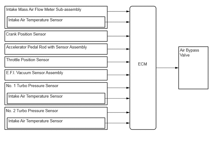
The ECM opens and closes the air bypass valve in accordance with driving conditions to prevent the surge phenomenon.
W146004E01
0.208,0.229 2.917,0.479 2.708,0.25 10 false Intake Mass Air Flow Meter Sub-assembly 0.281,0.583 2.99,0.833 2.708,0.25 10 false Intake Air Temperature Sensor 0.198,1.063 2.906,1.313 2.708,0.25 10 false Crank Position Sensor 0.208,1.5 3.146,1.719 2.938,0.219 10 false Accelerator Pedal Rod with Sensor Assembly 0.208,1.927 2.917,2.177 2.708,0.25 10 false Throttle Position Sensor 0.208,2.802 2.917,3.052 2.708,0.25 10 false No. 1 Turbo Pressure Sensor 0.281,3.156 2.99,3.406 2.708,0.25 10 false Intake Air Temperature Sensor 0.198,3.646 2.906,3.896 2.708,0.25 10 false No. 2 Turbo Pressure Sensor 4.646,2.073 5.104,2.271 0.458,0.198 10 false ECM 6.052,1.604 6.76,2.135 0.708,0.531 10 false Air Bypass Valve 0.208,2.365 2.917,2.615 2.708,0.25 10 false E.F.I. Vacuum Sensor Assembly 0.281,3.99 2.99,4.24 2.708,0.25 10 false Intake Air Temperature Sensor