EXTERIOR PANELS / TRIM BODY STRUCTURE DETAILS SAFETY FEATURES
FUNCTION
Impact Absorbing Structure for Frontal Collision
In order to enhance passenger protection performance during frontal collisions, a vehicle structure that optimally absorbs and disperses the impact load has been developed.
During a frontal collision, the collision load from the upper member (* 1 in illustration) is distributed to the rail, beltline, and rocker via the front body pillar.
During a frontal collision, the collision load from the upper member (* 1 in illustration) is distributed to the cowl reinforcement and installation panel reinforcement.
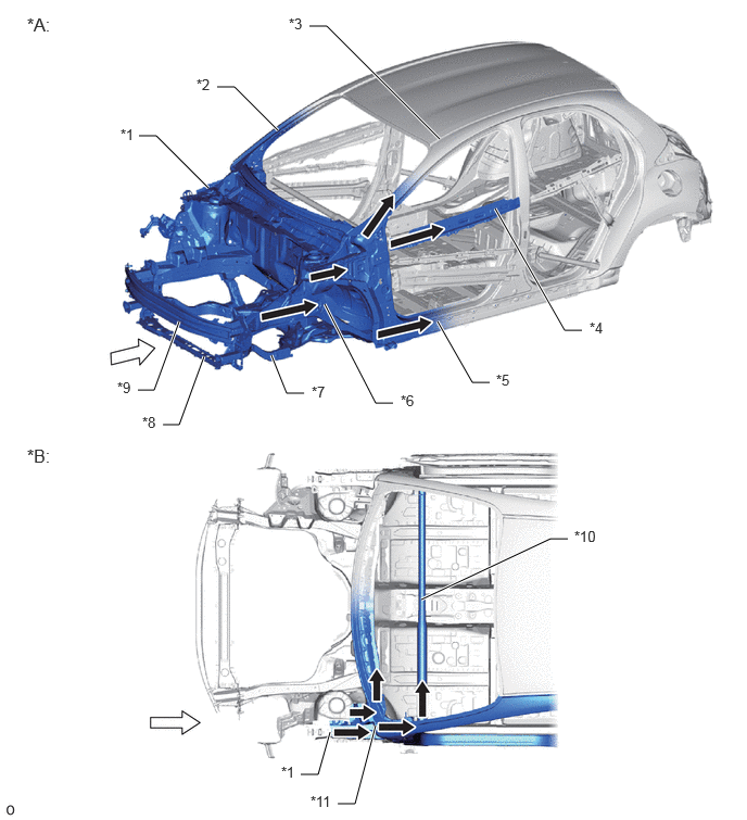
| *A | Frontal Collision (Full-lap) | *B | Frontal Collision (Offset) |
| *1 | Upper Member | *2 | Front Body Pillar |
| *3 | Roof Side Rail | *4 | Front Door Beltline Reinforcement |
| *5 | Rocker Panel | *6 | Front Side Member |
| *7 | Front Suspension Crossmember Sub-assembly | *8 | No. 2 Front Bumper Reinforcement |
| *9 | Front Bumper Reinforcement | *10 | Instrument Panel Reinforcement Assembly |
| *11 | Outer Cowl Top Panel Sub-assembly | - | - |

|
Front Impact Energy | 
|
Dissipate |
A front suspension crossmember sub-assembly that is integrated into the front suspension member has been adopted. As a result, the load at the beginning of the collision tends to be increased to enhance energy absorption efficiency, while also contributing to lowering the center of gravity of the vehicle.
By separating the suspension member from the body at the time of the frontal collision, the load in the second half of the collision tends to be reduced, enhancing occupant protection performance.
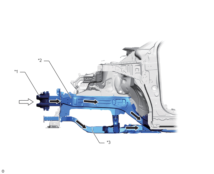
| *1 | Front Bumper Reinforcement | *2 | Front Side Member |
| *3 | Front Suspension Crossmember Sub-assembly | - | - |
|
|
Front Impact Energy |
|
Dissipate |
The outer cowl top panel sub-assembly is effectively shock-absorbed to prevent deformation of the door frame.
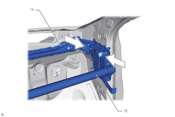
| *1 | Outer Cowl Top Panel Sub-assembly | *2 | Instrument Panel Reinforcement Assembly |
|
|
Front Impact Energy | - | - |
The front body pillar lower section has been widened to reduce deformation during a collision.
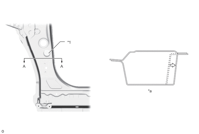
| *1 | Front Body Pillar Lower | - | - |
| *a | A-A Cross Section | - | - |
The front body pillar is molded integrally with the outer reinforcement, and the deformation of the cabin is suppressed by eliminating the chance of folding. In addition, the front body pillar and the rail are connected by spot welding.
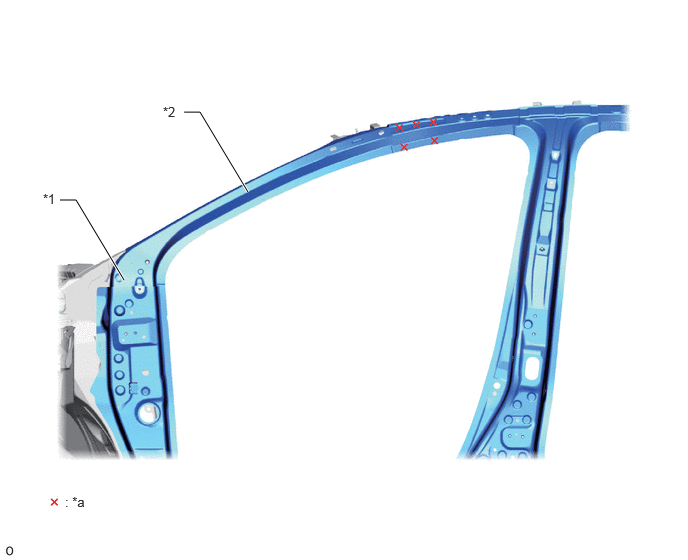
| *1 | Front Body Pillar | *2 | Roof Side Rail |
| *a | Spot Weld | - | - |
Impact Absorbing Structure for Side Collision
Hot-stamped steel, ultra high-tensile strength steel, and high tensile strength steel are used for the body frame to increase strength and suppress deformation of the cabin.
The center pillar outer reinforcement and front pillar outer reinforcement also use hot-stamped steel. In addition, the center pillar side member integrates the upper and lower to reduce deformation.
High tensile strength steel is used for the rail outer reinforcement, front pillar inner, rocker outer, and rocker inner to reduce cabin deformation.
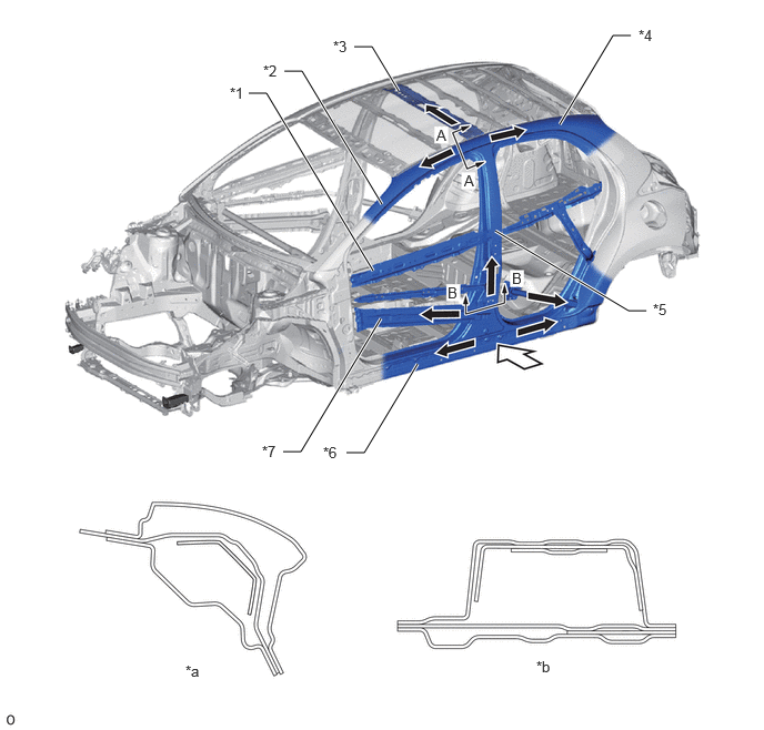
| *1 | Front Door Beltline Reinforcement | *2 | Front Body Pillar |
| *3 | Roof Panel Reinforcement Center | *4 | Roof Side Panel |
| *5 | Center Body Pillar | *6 | Rocker Panel |
| *7 | Impact Beam | - | - |
| *a | A - A Cross Section | *b | B - B Cross Section |
|
|
Impact Energy |
|
Dissipate |
Diagonal reinforcements are used for the rear door. As a result, door deformation is suppressed during collisions, helping enhance that the doors can be opened.*
- HINT:
-
*: 5 door models
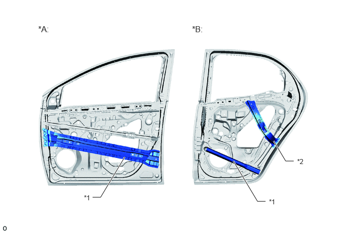
| *A | Front Door | *B | Rear Door |
| *1 | Impact Beam | *2 | Rear Door Rear Upper Frame Reinforcement LH |
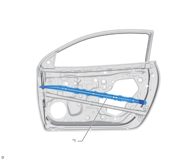
| *1 | Impact Beam | - | - |
The center roof panel reinforcement and the roof side rail are connected to each other by spot welds via a roof gusset, enhancing joint rigidity and thereby suppressing cabin deformation.
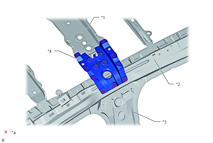
| *1 | Center Roof Panel Reinforcement | *2 | Roof Side Rail |
| *3 | Center Body Pillar | *4 | Roof Panel Reinforcement Bracket |
| *a | Spot Weld | - | - |