EA67F MANUAL TRANSMISSION / TRANSAXLE MANUAL TRANSAXLE SYSTEM DETAILS GEAR TRAIN
CONSTRUCTION
A twin output system has been adopted, with the No. 1 output shaft and No. 2 output shaft located on the outer circumference of the ring gear.
The 1st and Reverse (R), as well as the 4th and 5th drive gears are shared, achieving a more compact manual transaxle.
Low-resistance bearings have been adopted for the output shaft and differential shaft bearings, achieving increased power transmission efficiency.
By adopting various inter-axial distances from the input shaft to the No. 1 output shaft and No. 2 output shaft, a wide gear range was achieved.
Triple cone type synchronizer rings are used for the 1st, 2nd, and 3rd gears.
Double cone type synchronizer rings are used for the 4th gear.
Single cone type synchronizer rings are used for the 5th, 6th, and reverse (R) gears.
A constant-engagement type reverse (R) gear is used for enhanced shift feeling.
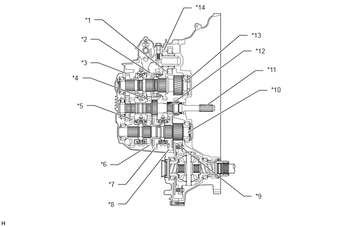
| *1 | Reverse Gear | *2 | 5th Driven Gear |
| *3 | 6th Gear Sub-assembly | *4 | 4th and 5th Drive Gear |
| *5 | 3rd Gear | *6 | 4th Gear |
| *7 | 2nd Gear | *8 | 1st Gear |
| *9 | Ring Gear | *10 | No. 1 Output Shaft |
| *11 | Input Shaft | *12 | 1st and Reverse Drive Gear |
| *13 | No. 2 Output Shaft | *14 | Reverse Idler Gear Sub-assembly |