AXLE AND DIFFERENTIAL DIFFERENTIAL SYSTEM DETAILS REAR DIFFERENTIAL
CONSTRUCTION
FD15FE Type Rear Differential.
The transmission coupling assembly (electronically controlled coupling) is located in front of the rear differential.
Die-cast aluminum construction is used for the rear differential carrier and rear differential retainer, achieving weight reduction.
Including the shapes of the various gears and the bearing locations, each of the component parts has been optimized, thereby achieving compactness.
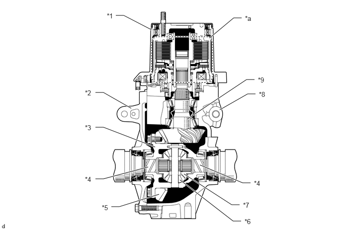
| *1 | Transmission Coupling Assembly | *2 | Rear Differential Retainer |
| *3 | Rear Differential Case | *4 | Rear Drive Shaft |
| *5 | Ring Gear | *6 | Pinion Gear |
| *7 | Side Gear | *8 | Rear Differential Carrier |
| *9 | Rear Drive Pinion | - | - |
| *a | Electromagnetic Control Coupling Portion | - | - |
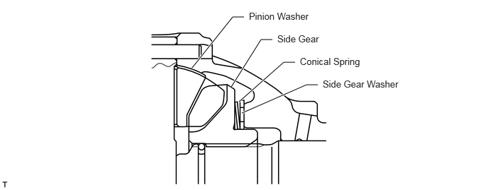
For the differential pre-torque mechanism, a conical disc spring is provided between the side gear and side gear washer of the differential portion, this generates frictional force at the sliding portion due to loading of the conical disc spring, providing enhanced take-off performance on low-friction road surfaces.
FD15 Type Torque-sensing Limited Slip Differential (TORSEN LSD)
The torque-sensing limited slip differential (TORSEN LSD) optimally distributes driving torque in response to accelerator operation, achieving high traction, steering, and driving stability performance.
The transmission coupling assembly (electronically controlled coupling) is located in front of the rear differential.
Die-cast aluminum construction is used for the rear differential carrier and rear differential retainer, achieving weight reduction.
Including the shapes of the various gears and the bearing locations, each of the component parts has been optimized, thereby achieving compactness.
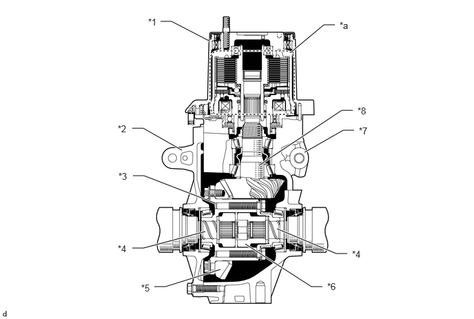
| *1 | Transmission Coupling Assembly | *2 | Rear Differential Retainer |
| *3 | Rear Differential Case | *4 | Rear Drive Shaft |
| *5 | Ring Gear | *6 | Side Gear |
| *7 | Rear Differential Carrier | *8 | Rear Drive Pinion |
| *a | Electromagnetic Control Coupling Portion | - | - |
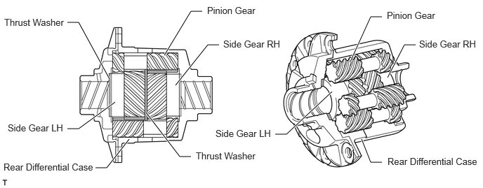
The rear differential case sub-assembly is composed of the differential case and 8 pinion gears, 2 side gears and 4 thrust washers.
For the pinion gears, 2 pinion gears are engaged to make 1 pair, and each of these is engaged with one of the side gears.
The pinion gears are supported in the holes provided in the differential case, and their design allows them to rotate on the side gear while also revolving around it.
OPERATION
Rear Differential Power Flow
The illustration below shows the flow of power transmitted from the propeller shaft:
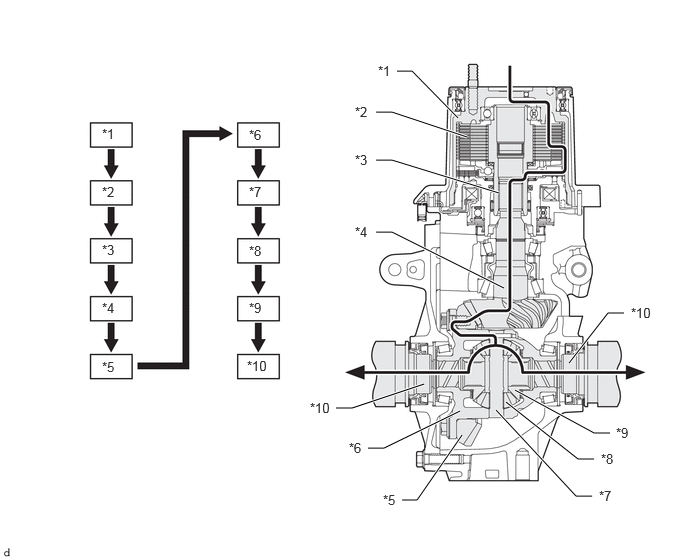
| *1 | Front Housing | *2 | Main Clutch |
| *3 | Shaft | *4 | Rear Drive Pinion |
| *5 | Ring Gear | *6 | Rear Differential Case |
| *7 | Pinion Shaft | *8 | Pinion Gear |
| *9 | Side Gear | *10 | Rear Drive Shaft |

|
Power Flow | - | - |
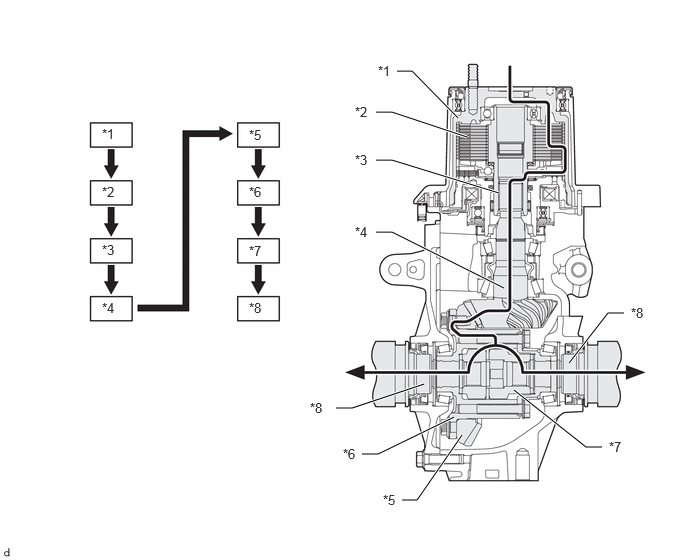
| *1 | Front Housing | *2 | Main Clutch |
| *3 | Shaft | *4 | Rear Drive Pinion |
| *5 | Ring Gear | *6 | Rear Differential Case |
| *7 | Side Gear | *8 | Rear Drive Shaft |
|
|
Power Flow | - | - |
Torque-sensing Limited Slip Differential (TORSEN LSD)
When driving in a straight line, the left and right drive shafts rotate in the same direction at the same frequency, and so the differential case, pinion gears and side gears all rotate together as a single unit, and drive force is transferred in the following sequence.
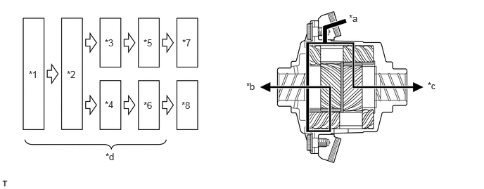
| *1 | Ring Gear | *2 | Rear Differential Case |
| *3 | Pinion Gear RH | *4 | Pinion Gear LH |
| *5 | Side Gear RH | *6 | Side Gear LH |
| *7 | Rear Drive Shaft RH | *8 | Rear Drive Shaft LH |
| *a | Power Flow (input : 100) | *b | Output : 50 |
| *c | Output : 50 | *d | Rotate together as a single unit. |
When the vehicle is turning, to simplify the explanation, it should be assumed that the differential case is fixed in place.
When the left side gear is rotated to the left, the left pinion gear (engaged with the left side gear) rotates to the right, and the paired right pinion gear rotates to the left.
Then, the right side gear rotates in the opposite direction (to the right) of the left side gear, and thereby differential is performed
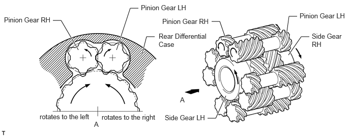
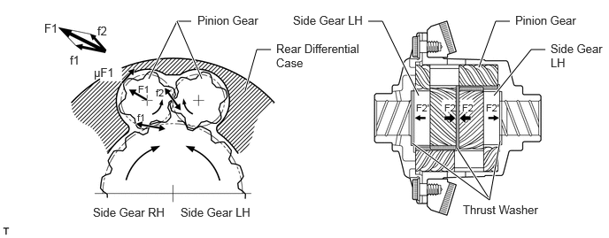
Differential limiting is mainly performed via friction in 2 locations: between the tips of the pinion gear teeth and the inner wall surface of the differential case, as well as between the side gear end face and the thrust washers
Proportional to the input force, the pinion gear-to-side gear engagement counterforce f1 and the pinion gear-to-pinion gear engagement counterforce f2 combine to make the composite force F1, which works in the direction of pushing the pinion gear against the differential case, and the frictional force μF1 generated between the tips of the pinion gear teeth and the differential case inner wall works to push the pinion gear in the direction to stop its self-rotation.
Between the left and right side gears, due to the twist angle of the differential gear, the thrust force F2 is generated in the axial direction, and the frictional force μF2 between the side gear end face and the thrust washer works in the direction to stop the self-rotation of the side gear. (During deceleration, the thrust force F2' is generated.)