G16E-GTS ENGINE MECHANICAL ENGINE UNIT DETAILS CAMSHAFT
CONSTRUCTION
To handle higher outputs, an assembled camshaft made from a hollow shaft combined with cam pieces has been adopted.
The cam profile has been designed with an indented R (radius). This results in increased valve lift when the valve begins to open and finishes closing, helping to achieve enhanced output performance.
A timing rotor for the camshaft position sensor is provided on the intake camshaft sub-assembly and exhaust camshaft sub-assembly.
The cam that drives the fuel pump assembly (for high pressure) is positioned between the No. 2 cylinder and the No. 3 cylinder to achieve size reduction. Also, a pump cam with 3 peaks is used in the cam that drives the fuel pump assembly (for high pressure) and by synchronizing fuel pressure-feeding and fuel injection, the difference in fuel pressure between cylinders is reduced.
The vacuum pump assembly is driven by the end of the exhaust camshaft sub-assembly.
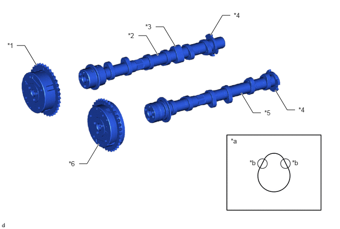
| *1 | Camshaft Timing Exhaust Gear Assembly | *2 | Exhaust Camshaft Sub-assembly |
| *3 | Cam (for Powering the Fuel Pump) | *4 | Timing Rotor |
| *5 | Intake Camshaft Sub-assembly | *6 | Camshaft Timing Gear Assembly |
| *a | Cam Profile | *b | Indented R Portion of Cam |