Home › Power Source / Network › NETWORKING › CAN COMMUNICATION SYSTEM (for Gasoline Model) › from 2020.09
NM36W0E _57 Power Source / Network _088338 NETWORKING _0421310 CAN COMMUNICATION SYSTEM(for Gasoline Model) GE GENERAL F

NETWORKING  CAN COMMUNICATION SYSTEM(for Gasoline Model)  GENERAL  GENERAL  


OUTLINE


a.

Controller Area Network (CAN) communication, which makes high-speed communication possible, is used as a multiplex communication system* to simplify vehicle wire harnesses and achieve high-speed communication.

HINT:

*: The multiplex communication system connects several ECUs together with one communication line so that they can exchange data with each other. As a result, additional wiring is not required when integrating systems and adding functions.


b.

The CAN communication system is subdivided into 2 systems (CAN/CAN FD) based on communication protocol and communication speed. The CAN*1 system communicates at 500 kbps, and the CAN FD*2 system communicates at 2 Mbps.

HINT:

*1: CAN, an abbreviation of "Controller Area Network", is an ISO (International Organization for Standardization)-compliant serial communication.

*2: CAN FD is an abbreviation for CAN with Flexible Data rate, and is a transmission protocol that extends the CAN protocol to enable high-speed transmission of even larger amounts of data.


CAN and CAN FD Specifications
Protocol CAN CAN FD
Communication Speed 500 kbps 2 Mbps
Communication Wire Twisted-pair Wire
Drive Type Differential Voltage Drive
Data Length 1 to 8 Byte (Variable) 1 to 8, 12, 16, 20, 24, 32, 48, 64 Byte (Variable)


c.

Communication Wire

i.

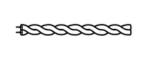
A twisted pair of wires is used for CAN communication.

Communication Wire Outline
Twisted-pair Wire
Y120996

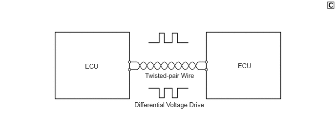
This communication wire is a pair of twisted wires. Communication is driven by applying different voltages to the 2 lines in order to send a single signal. The bus line has a high line (2.5 V to 3.5 V of voltage is applied) and a low line (1.5 V to 2.5 V of voltage is applied). This system, which is called a "differential voltage drive", reduces the effects of electrical noise.

Y251626E01
1.813,1.333 2.177,1.531 0.365,0.198 10 false ECU 5.073,1.323 5.417,1.573 0.344,0.25 10 false ECU 3.094,1.531 4.292,1.833 1.198,0.302 10 false Twisted-pair Wire 2.865,2.156 4.458,2.521 1.594,0.365 10 false Differential Voltage Drive


d.

A CAN communication system is used to send information and data for multiple items, which have been converted into digital signals by the communication circuit, over one communication line (twisted-pair wire). As a result, the communication systems connected to the input systems (such as sensors and switches), control units and output systems (such as motors), achieve simplified vehicle wire harnesses.


e.

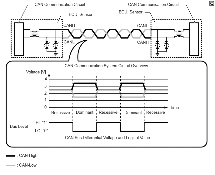
The CAN communication system consists of a pair of two communication lines (buses), CAN-High and CAN-Low. The system uses the differential voltage of the communication lines to determine the bus level* and transmits a digital signal at 500 kbps or 2 Mbps using an exclusive communication protocol (communication rules).

HINT:

*: The bus level has a dominant level and a recessive level, and the CAN communication system logically calculates the dominant level as "0" and the recessive level as "1".

Y251627E01
0.625,0.75 0.917,0.167 0.917,0.167 1.083,0.167 true 1.917,0.75 2.042,0.5 2.042,0.5 2.208,0.5 true 6.5,0.75 6.208,0.167 6.208,0.167 6.042,0.167 true 5.167,0.75 5,0.417 5,0.417 4.833,0.417 true 1.156,0.063 2.948,0.385 1.792,0.323 10 false CAN Communication Circuit 2.292,0.396 4.083,0.719 1.792,0.323 10 false ECU, Sensor 2.115,0.76 2.604,1.104 0.49,0.344 10 false CANH 2.125,1.313 2.615,1.656 0.49,0.344 10 false CANL 4.573,1.323 5.063,1.667 0.49,0.344 10 false CANH 4.573,0.771 5.063,1.115 0.49,0.344 10 false CANL 4.271,0.063 6.063,0.385 1.792,0.323 10 false CAN Communication Circuit 3.958,0.313 4.865,0.635 0.906,0.323 10 false ECU, Sensor 0.875,2.313 1.667,2.656 0.792,0.344 10 false Voltage [V] 1.49,2.542 1.604,2.719 0.115,0.177 10 false 4 1.479,2.792 1.594,2.969 0.115,0.177 10 false 3 1.479,3.021 1.594,3.198 0.115,0.177 10 false 2 1.479,3.229 1.594,3.406 0.115,0.177 10 false 1 0.333,4.125 1.125,4.469 0.792,0.344 10 false Bus Level 1.479,3.479 1.594,3.656 0.115,0.177 10 false 0 1.188,4 1.646,4.25 0.458,0.25 10 false HI="1" 1.167,4.271 1.667,4.521 0.5,0.25 10 false LO="0" 1.708,3.667 2.5,4.01 0.792,0.344 10 false Recessive 4.875,3.656 5.667,4 0.792,0.344 10 false Recessive 3.292,3.656 4.083,4 0.792,0.344 10 false Recessive 2.531,3.656 3.323,4 0.792,0.344 10 false Dominant 4.146,3.667 4.938,4.01 0.792,0.344 10 false Dominant 5.667,3.5 6,3.833 0.333,0.333 10 false Time 2.167,4.5 5.083,4.833 2.917,0.333 10 false CAN Bus Differential Voltage and Logical Value 0.563,5.094 2.063,5.427 1.5,0.333 10 false : CAN-High 0.563,5.417 2.063,5.75 1.5,0.333 10 false : CAN-Low 2.156,2.104 5.271,2.354 3.115,0.25 10 false CAN Communication System Circuit Overview


f.

The terminating resistors for each bus are located as shown in the following table.

Bus Terminating Resistor Location Gateway Function Gateway Destination

*1: AWD models or models with tire pressure warning system

*2: Models with CAN compatible optional devices

CAN Diagnosis Bus Central Gateway ECU (Network Gateway ECU) Central Gateway ECU (Network Gateway ECU)
·

Bus 1

·

Bus 2

·

Bus 3

·

Bus 4

·

Bus 5

·

Bus 6*1

·

Bus 7*2


CAN Bus 1
·

Central Gateway ECU (Network Gateway ECU)

·

No. 1 CAN Junction Terminal


Central Gateway ECU (Network Gateway ECU)
·

Diagnosis Bus

·

Bus 2

·

Bus 3

·

Bus 4

·

Bus 5

·

Bus 6*1

·

Bus 7*2


CAN Bus 2
·

Central Gateway ECU (Network Gateway ECU)

·

ECM


Central Gateway ECU (Network Gateway ECU)
·

Diagnosis Bus

·

Bus 1

·

Bus 3

·

Bus 4

·

Bus 5

·

Bus 6*1

·

Bus 7*2


CAN Bus 3
·

Central Gateway ECU (Network Gateway ECU)

·

Combination Meter Assembly


Central Gateway ECU (Network Gateway ECU)
·

Diagnosis Bus

·

Bus 1

·

Bus 2

·

Bus 4

·

Bus 5

·

Bus 6*1

·

Bus 7*2


CAN Bus 4
·

Central Gateway ECU (Network Gateway ECU)

·

Power Steering ECU Assembly


Central Gateway ECU (Network Gateway ECU)
·

Diagnosis Bus

·

Bus 1

·

Bus 2

·

Bus 3

·

Bus 5

·

Bus 6*1

·

Bus 7*2


CAN Bus 5
·

Central Gateway ECU (Network Gateway ECU)

·

Main Body ECU (Multiplex Network Body ECU)


Central Gateway ECU (Network Gateway ECU)
·

Diagnosis Bus

·

Bus 1

·

Bus 2

·

Bus 3

·

Bus 4

·

Bus 6*1

·

Bus 7*2


CAN Bus 6*1 Central Gateway ECU (Network Gateway ECU) Central Gateway ECU (Network Gateway ECU)
·

Diagnosis Bus

·

Bus 1

·

Bus 2

·

Bus 3

·

Bus 4

·

Bus 5

·

Bus 7*2


CAN Bus 7*2 Central Gateway ECU (Network Gateway ECU) Central Gateway ECU (Network Gateway ECU)
·

Diagnosis Bus

·

Bus 1

·

Bus 2

·

Bus 3

·

Bus 4

·

Bus 5

·

Bus 6*1


CAN Chassis Local Bus
·

Central Gateway ECU (Network Gateway ECU)

·

Skid Control ECU (Brake Actuator Assembly)


- -


g.

CAN and CAN FD Communication Protocol (Communication Rules)

i.

The CAN communication system is a type of multiplex communication system that uses one communication line for all devices that make up the network and makes it possible to send and receive data while offsetting the communication timing. In order to do so, communication is performed according to a communication protocol (communication rules) that is shared by the devices. This communication protocol helps communication be performed smoothly and securely.


ii.

The CAN communication protocol uses the Carrier Sense Multiple Access with Collision Detection (CSMA/CD) protocol* as the rules for sending data via the communication line. This protocol allows all devices to share one communication line while retaining the right to start sending data.

HINT:

*: This is a type of communication access control where devices constantly detect the condition of the communication line and only send data when no other data is being sent. In addition, when the system detects that a data collision has occurred (data was simultaneously sent from another device), it waits for a certain period of time before resending the data.


iii.

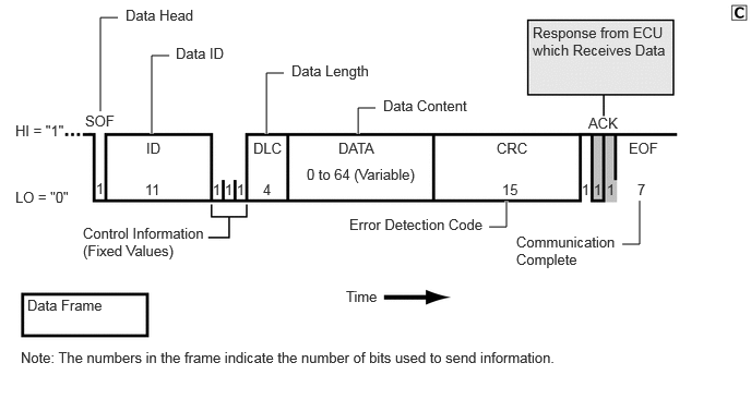
Data used by the CAN communication system is composed of a single frame that includes parts such as "ID", "RTR", "DLC", "DATA", "CRC" and "ACK".
CAN Communication Data Frame
Y257910E01
0.958,1.063 0.958,0.167 0.958,0.167 1.125,0.167 true 1.448,1.281 1.448,0.531 1.448,0.531 1.615,0.531 true 2.542,1.281 2.542,0.698 2.542,0.698 2.708,0.698 true 3.417,1.281 3.417,1.031 3.417,1.031 3.583,1.031 true 4.667,2.167 4.833,2.167 4.833,2.167 4.833,1.917 true 5.938,2.333 6.104,2.333 6.104,2.333 6.104,1.917 true 0.146,1.167 0.667,1.354 0.521,0.188 10 false HI = "1" 0.146,1.802 0.75,1.99 0.604,0.188 10 false LO = "0" 0.917,1.719 1.083,1.99 0.167,0.271 10 false 1 1.385,1.729 1.719,2.063 0.333,0.333 10 false 11 2.031,1.729 2.198,2 0.167,0.271 10 false 1 2.146,1.729 2.313,2 0.167,0.271 10 false 1 2.26,1.729 2.427,2 0.167,0.271 10 false 1 2.51,1.729 2.844,2.063 0.333,0.333 10 false 4 1.396,1.333 1.729,1.667 0.333,0.333 10 false ID 2.417,1.333 2.75,1.667 0.333,0.333 10 false DLC 3.229,1.333 3.729,1.667 0.5,0.333 10 false DATA 4.74,1.333 5.24,1.667 0.5,0.333 10 false CRC 4.792,1.729 5.125,2.063 0.333,0.333 10 false 15 5.552,1.729 5.719,2 0.167,0.271 10 false 1 5.667,1.729 5.833,2 0.167,0.271 10 false 1 5.792,1.729 5.958,2 0.167,0.271 10 false 1 6.083,1.729 6.25,2 0.167,0.271 10 false 7 0.813,1.073 1.146,1.406 0.333,0.333 10 false SOF 5.615,1.094 5.948,1.427 0.333,0.333 10 false ACK 0.792,2.146 1.979,2.563 1.188,0.417 10 false Control Information (Fixed Values) 2.927,1.583 4.083,1.833 1.156,0.25 10 false 0 to 64 (Variable) 3.302,2.75 3.969,3 0.667,0.25 10 false Time 1.198,0.063 2.031,0.396 0.833,0.333 10 false Data Head 1.677,0.427 2.51,0.76 0.833,0.333 10 false Data ID 2.781,0.594 3.615,0.927 0.833,0.333 10 false Data Length 3.656,0.927 4.49,1.26 0.833,0.333 10 false Data Content 0.26,2.833 1.094,3.167 0.833,0.333 10 false Data Frame 3.333,2.063 4.833,2.313 1.5,0.25 10 false Error Detection Code 5.083,0.229 6.417,0.813 1.333,0.583 10 false Response from ECU which Receives Data 6,1.333 6.333,1.667 0.333,0.333 10 false EOF 4.927,2.229 5.927,2.646 1,0.417 10 false Communication Complete 0.198,3.333 6.552,3.667 6.354,0.333 10 false Note: The numbers in the frame indicate the number of bits used to send information.


iv.

Data used by the CAN FD communication system is composed of a single frame that includes parts such as "ID", "RRS", "FDF", "DLC", "DATA", "CRC" and "ACK".
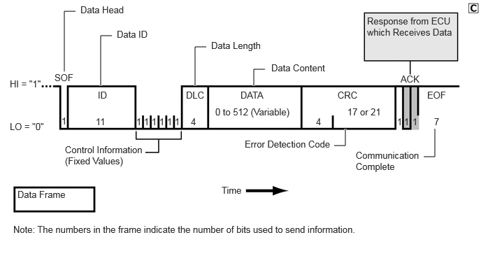
CAN FD Communication Data Frame
Y257911E01
0.958,1.063 0.958,0.167 0.958,0.167 1.125,0.167 true 1.5,1.281 1.5,0.531 1.5,0.531 1.667,0.531 true 2.906,1.281 2.906,0.698 2.906,0.698 3.073,0.698 true 3.781,1.281 3.781,1.031 3.781,1.031 3.948,1.031 true 4.979,2.167 5.146,2.167 5.146,2.167 5.146,1.917 true 6.313,2.333 6.479,2.333 6.479,2.333 6.479,1.917 true 0.146,1.167 0.667,1.354 0.521,0.188 10 false HI = "1" 0.146,1.802 0.75,1.99 0.604,0.188 10 false LO = "0" 0.917,1.719 1.083,1.99 0.167,0.271 10 false 1 1.427,1.729 1.76,2.063 0.333,0.333 10 false 11 2.031,1.729 2.198,2 0.167,0.271 10 false 1 2.146,1.729 2.313,2 0.167,0.271 10 false 1 2.26,1.729 2.427,2 0.167,0.271 10 false 1 2.844,1.729 3.177,2.063 0.333,0.333 10 false 4 1.458,1.333 1.792,1.667 0.333,0.333 10 false ID 2.771,1.333 3.104,1.667 0.333,0.333 10 false DLC 3.583,1.333 4.083,1.667 0.5,0.333 10 false DATA 5.031,1.333 5.531,1.667 0.5,0.333 10 false CRC 4.708,1.729 5.042,2.063 0.333,0.333 10 false 4 5.917,1.729 6.083,2 0.167,0.271 10 false 1 6.021,1.729 6.188,2 0.167,0.271 10 false 1 6.146,1.729 6.313,2 0.167,0.271 10 false 1 6.469,1.729 6.635,2 0.167,0.271 10 false 7 0.813,1.073 1.146,1.406 0.333,0.333 10 false SOF 5.969,1.094 6.302,1.427 0.333,0.333 10 false ACK 0.969,2.146 2.156,2.563 1.188,0.417 10 false Control Information (Fixed Values) 3.208,1.583 4.438,1.844 1.229,0.26 10 false 0 to 512 (Variable) 3.302,2.75 3.969,3 0.667,0.25 10 false Time 1.198,0.063 2.031,0.396 0.833,0.333 10 false Data Head 1.74,0.427 2.573,0.76 0.833,0.333 10 false Data ID 3.146,0.594 3.979,0.927 0.833,0.333 10 false Data Length 4.042,0.927 4.875,1.26 0.833,0.333 10 false Data Content 0.26,2.813 1.094,3.146 0.833,0.333 10 false Data Frame 3.646,2.063 5.146,2.313 1.5,0.25 10 false Error Detection Code 5.469,0.229 6.802,0.813 1.333,0.583 10 false Response from ECU which Receives Data 6.365,1.333 6.698,1.667 0.333,0.333 10 false EOF 5.302,2.229 6.302,2.646 1,0.417 10 false Communication Complete 0.198,3.333 6.552,3.667 6.354,0.333 10 false Note: The numbers in the frame indicate the number of bits used to send information. 5.177,1.583 5.896,1.833 0.719,0.25 10 false 17 or 21 2.375,1.729 2.542,2 0.167,0.271 10 false 1 2.49,1.729 2.656,2 0.167,0.271 10 false 1 2.604,1.729 2.771,2 0.167,0.271 10 false 1


h.

A diagnostic tool can be connected to perform diagnostic communication. Refer to the Repair Manual for details.