Home › Drivetrain › CLUTCH › CLUTCH SYSTEM › from 2020.09
NM36W0E _52 Drivetrain _088260 CLUTCH _0420876 CLUTCH SYSTEM DE DETAILS F

CLUTCH  CLUTCH SYSTEM  DETAILS  CLUTCH COVER  


CONSTRUCTION


a.

A diaphragm spring is used in the clutch cover assembly.


b.

For vehicles with the EA67F type manual transaxle, a TAC (Travel Adjusted Clutch) has been adopted, the TAC (Travel Adjusted Clutch) suppresses the increase in pedal force caused by clutch disc wear, thereby maintaining a comfortable operation feel.
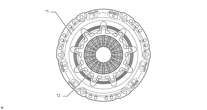
For EC6E Manual Transaxle Models
X145825C01
1.75,0.417 1.917,0.417 1.917,0.417 2.615,1.063 true 2.167,3.333 2.333,3.333 2.333,3.333 3.219,2.51 true 1.552,0.344 1.865,0.5 0.313,0.156 10 false *1 1.958,3.26 2.271,3.417 0.313,0.156 10 false *2
*1 Clutch Cover Assembly *2 Diaphragm Spring


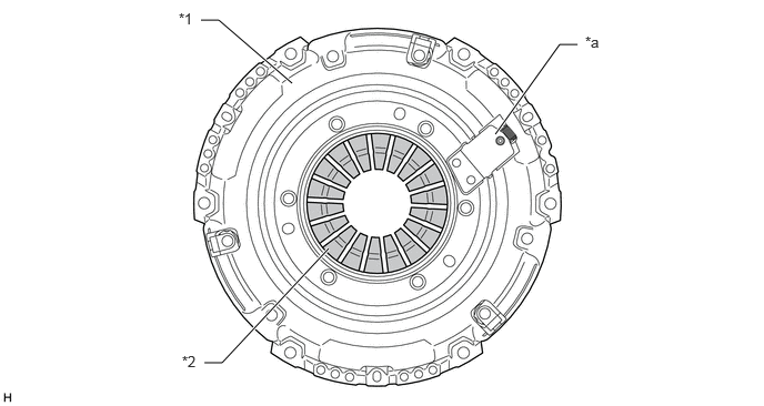
For C551 Manual Transaxle Models
X145876C01
1.75,0.417 1.917,0.417 1.917,0.417 2.49,1.198 true 2.167,3.333 2.333,3.333 2.333,3.333 3.219,2.417 true 1.563,0.313 1.875,0.469 0.313,0.156 10 false *1 1.958,3.229 2.271,3.385 0.313,0.156 10 false *2
*1 Clutch Cover Assembly *2 Diaphragm Spring


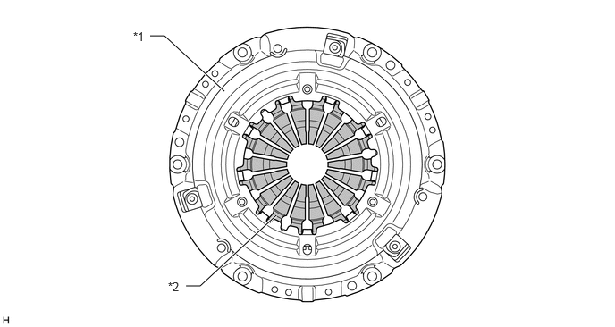
For EA67F Manual Transaxle Models
X147245C01
1.885,0.188 2.052,0.188 2.052,0.188 2.74,0.781 true 1.917,3.406 2.083,3.406 2.083,3.406 3.083,2.333 true 5.417,0.417 5.25,0.417 5.25,0.417 4.646,1.26 true 1.677,0.094 1.99,0.25 0.313,0.156 10 false *1 1.708,3.313 2.021,3.469 0.313,0.156 10 false *2 5.49,0.313 5.802,0.469 0.313,0.156 10 false *a
*1 Clutch Cover Assembly *2 Diaphragm Spring
*a TAC mechanism - -


OPERATION


a.

TAC (Travel Adjusted Clutch) compensation mechanism

i.

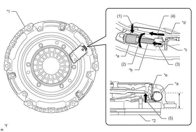
The TAC (Travel Adjusted Clutch) compensation mechanism is such that clutch disc wear causes the main spring to rotate the pinion gear.


ii.

As the spindle moves, the nut travels accordingly, which rotates the adjuster ring to perform compensation of the diaphragm spring positioning.


iii.

By suppressing changes to the diaphragm spring positioning, increases in clutch release loading and pedal force are suppressed.
X147246C02
0.417,0.417 0.583,0.417 0.583,0.417 0.917,1 true 4.5,0.583 4.667,0.583 4.667,0.583 4.833,0.927 true 6.167,0.583 6,0.583 6,0.583 5.75,1.25 true 6.583,0.844 6.417,0.844 6.417,0.844 6.25,1.26 true 6.667,1.833 6.5,1.833 6.5,1.833 5.833,1.5 true 6.333,2.354 6.167,2.354 6.167,2.354 5.75,1.604 true 4.917,2.552 5.083,2.552 5.083,2.552 5.417,1.552 true 4.667,2.333 4.833,2.333 4.833,2.333 5.083,1.583 true 4.417,2.052 4.583,2.052 4.583,2.052 4.75,1.552 true 5.917,2.75 5.75,2.75 5.75,2.75 5.563,3.229 true 6.333,3.083 6.167,3.083 6.167,3.083 5.865,3.427 true 6.083,4.333 5.917,4.333 5.917,4.333 5.333,3.667 true 5.5,4.417 5.333,4.417 5.333,4.417 5.083,4.167 true 0.24,0.333 0.552,0.49 0.313,0.156 10 false *1 5.563,4.323 5.875,4.479 0.313,0.156 10 false *2 4.229,1.958 4.542,2.115 0.313,0.156 10 false *a 4.719,2.469 5.031,2.625 0.313,0.156 10 false *b 6.729,1.729 7.042,1.885 0.313,0.156 10 false *c 6.656,0.74 6.969,0.896 0.313,0.156 10 false *d 5.99,2.656 6.302,2.813 0.313,0.156 10 false *e 0.167,4.51 0.479,4.667 0.313,0.156 10 false *f 6.396,2.969 6.708,3.125 0.313,0.156 10 false *a 4.281,0.5 4.594,0.656 0.313,0.156 10 false (1) 6.24,0.5 6.552,0.656 0.313,0.156 10 false (4) 6.406,2.26 6.719,2.417 0.313,0.156 10 false (3) 4.438,2.26 4.75,2.417 0.313,0.156 10 false (2) 6.156,4.229 6.469,4.385 0.313,0.156 10 false (5)
*1 Clutch Cover Assembly *2 Clutch Disc Assembly
*a Pinion Gear *b Spindle
*c Nut *d Adjuster Ring
*e Main Spring *f The illustrations shown are examples only.


NO. operation
(1) Clutch disc wear causes the main spring to rotate the pinion gear.
(2) As the pinion gear rotates, the spindle also rotates.
(3) Rotation of the spindle causes the nut to move linearly.
(4) The linear movement of the nut causes the adjuster ring to rotate, adjusting the position of the pressure plate.
(5) The adjustment of the pressure plate position compensates for the height of the worn portion of the clutch disc, reducing the loading.