LIGHTING (EXT) LIGHTING SYSTEM LO-beam Headlight does not Illuminate
DESCRIPTION
The main body ECU (multiplex network body ECU) controls the low beam headlights.
WIRING DIAGRAM
for LED Headlight
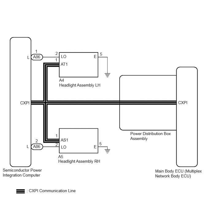
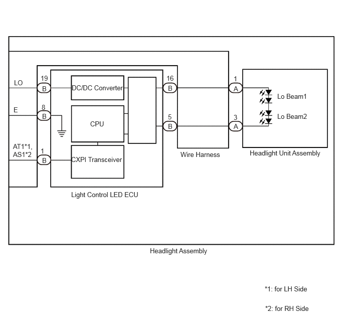
HEADLIGHT ASSEMBLY CIRCUIT (for LED Type)
for Halogen Headlight
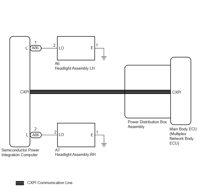
CAUTION / NOTICE / HINT
- NOTICE:
- ·
Before replacing the main body ECU (multiplex network body ECU), refer to Service Bulletin.*1
·First perform the communication function inspections in How to Proceed with Troubleshooting to confirm that there are no CAN communication malfunctions before troubleshooting this symptom.
Click hereVehicle Exterior>LIGHTING (EXT)>LIGHTING SYSTEM>HOW TO PROCEED WITH TROUBLESHOOTING
·First perform the communication function inspections in How to Proceed with Troubleshooting to confirm that there are no CXPI communication malfunctions before troubleshooting this symptom.
Click hereVehicle Exterior>LIGHTING (EXT)>LIGHTING SYSTEM>HOW TO PROCEED WITH TROUBLESHOOTING
*1: w/ Entry and Start System
PROCEDURE
Enter the following menus: Body Electrical / Main Body / Active Test.
Perform the Active Test according to the display on the GTS.
- Body Electrical > Main Body > Active Test
-
Tester Display Measurement Item Control Range Diagnostic Note Low Beam Headlight Low beam headlights OFF or ON -
- Body Electrical > Main Body > Active Test
-
Tester Display Low Beam Headlight - 50004 449 56
- OK:
Low beam headlights illuminate.
- Result:
Result Proceed to OK A NG (LH side low beam light does not illuminate.) (for LED Headlight) B NG (RH side low beam light does not illuminate.) (for LED Headlight) C NG (LH side low beam light does not illuminate.) (for Halogen Headlight) D NG (RH side low beam light does not illuminate.) (for Halogen Headlight) E
A
B
C
D
E
Disconnect the A4 headlight assembly LH connector.
Measure the voltage according to the value(s) in the table below.
- Standard Voltage:
Tester Connection Condition Specified Condition A4-2 (LO) - Body ground Light control switch in head position 11 to 14 V
- Result:
Proceed to OK NG
OK
NG
Measure the resistance according to the value(s) in the table below.
- Standard Resistance:
Tester Connection Condition Specified Condition A4-5 (E) - Body ground Always Below 1 Ω
- Result:
Proceed to OK NG
OK
NG
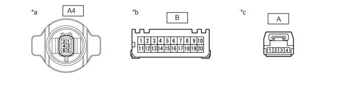
| *a | Component without harness connected
(to Wire Harness) |
*b | Component without harness connected
(to Light Control LED ECU) |
| *c | Component without harness connected
(to Headlight Unit Assembly) |
- | - |
Remove the headlight assembly LH.
Click hereVehicle Exterior>LIGHTING (EXT)>HEADLIGHT ASSEMBLY (for LED Headlight)>REMOVAL
Remove the Wire Harness.
Click hereVehicle Exterior>LIGHTING (EXT)>HEADLIGHT ASSEMBLY (for LED Headlight)>DISASSEMBLY
Measure the resistance according to the value(s) in the table below.
- Standard Resistance:
Tester Connection Condition Specified Condition A-[1] - B-[16] Always Below 1 Ω A-[3] - B-[5] Always Below 1 Ω A4-2 (LO) - B-[19] Always Below 1 Ω A4-5 (E) - B-[8] Always Below 1 Ω
- Result:
Proceed to OK NG
OK
NG
Interchange the light control LED ECU LH with RH and connect the connectors to them.
- Result:
Proceed to NEXT
NEXT
Check that the low beam headlight operates normally.
- OK:
Low beam headlight operates normally.
- Result:
Proceed to OK NG
OK
NG
Disconnect the A5 headlight assembly RH connector.
Measure the voltage according to the value(s) in the table below.
- Standard Voltage:
Tester Connection Condition Specified Condition A5-2 (LO) - Body ground Light control switch in head position 11 to 14 V
- Result:
Proceed to OK NG
OK
NG
Measure the resistance according to the value(s) in the table below.
- Standard Resistance:
Tester Connection Condition Specified Condition A5-5 (E) - Body ground Always Below 1 Ω
- Result:
Proceed to OK NG
OK
NG
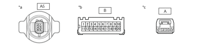
| *a | Component without harness connected
(to Wire Harness) |
*b | Component without harness connected
(to Light Control LED ECU) |
| *c | Component without harness connected
(to Headlight Unit Assembly) |
- | - |
Remove the headlight assembly RH.
Click hereVehicle Exterior>LIGHTING (EXT)>HEADLIGHT ASSEMBLY (for LED Headlight)>REMOVAL
Remove the Wire Harness.
Click hereVehicle Exterior>LIGHTING (EXT)>HEADLIGHT ASSEMBLY (for LED Headlight)>DISASSEMBLY
Measure the resistance according to the value(s) in the table below.
- Standard Resistance:
Tester Connection Condition Specified Condition A-[1] - B-[16] Always Below 1 Ω A-[3] - B-[5] Always Below 1 Ω A5-2 (LO) - B-[19] Always Below 1 Ω A5-5 (E) - B-[8] Always Below 1 Ω
- Result:
Proceed to OK NG
OK
NG
Interchange the light control LED ECU RH with LH and connect the connectors to them.
Click hereVehicle Exterior>LIGHTING (EXT)>HEADLIGHT ASSEMBLY (for LED Headlight)>DISASSEMBLY
- Result:
Proceed to NEXT
NEXT
Check that the low beam headlight operates normally.
- OK:
Low beam headlight operates normally.
- Result:
Proceed to OK NG
OK
NG
Disconnect the A6 headlight assembly LH connector.
Measure the voltage according to the value(s) in the table below.
- Standard Voltage:
Tester Connection Condition Specified Condition A6-2 (LO) - Body ground Light control switch in head position Below 1 V
- Result:
Proceed to OK NG
OK
NG
Measure the resistance according to the value(s) in the table below.
- Standard Resistance:
Tester Connection Condition Specified Condition A6-5 (E) - Body ground Always Below 1 Ω
- Result:
Proceed to OK NG
OK
NG
Disconnect the A7 headlight assembly RH connector.
Measure the voltage according to the value(s) in the table below.
- Standard Voltage:
Tester Connection Condition Specified Condition A7-2 (LO) - Body ground Light control switch in head position Below 1 V
- Result:
Proceed to OK NG
OK
NG
Measure the resistance according to the value(s) in the table below.
- Standard Resistance:
Tester Connection Condition Specified Condition A7-1 (E) - Body ground Always Below 1 Ω
- Result:
Proceed to OK NG
OK
NG