SEAT BELT SEAT BELT WARNING SYSTEM TERMINALS OF ECU
CHECK MAIN BODY ECU (MULTIPLEX NETWORK BODY ECU) AND POWER DISTRIBUTION BOX ASSEMBLY
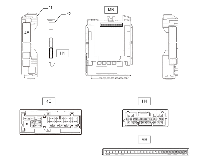
| *1 | Power Distribution Box Assembly | *2 | Main Body ECU (Multiplex Network Body ECU) |
Remove the main body ECU (multiplex network body ECU) from the power distribution box assembly.
Click herePower Source / Network>POWER DISTRIBUTION>MAIN BODY ECU>REMOVAL
Reconnect the power distribution box assembly connectors.
Measure the resistance and voltage according to the value(s) in the table below.
- HINT:
-
Measure the values on the wire harness side with the connector disconnected.
| Terminal No. (Symbol) | Wiring Color | Terminal Description | Condition | Specified Condition |
|---|---|---|---|---|
| MB-26 (BECU) - Body ground | - | Auxiliary battery power supply | Ignition switch off | 11 to 14 V |
| MB-27 (IGR) - Body ground | - | Ignition power supply (IG signal) | Ignition switch ON | 11 to 14 V |
| Ignition switch off | Below 1 V | |||
| MB-13 (GND1) - Body ground | - | Ground | Always | Below 1 Ω |
Install the main body ECU (multiplex network body ECU) to the power distribution box assembly.
Measure the resistance and voltage according to the value(s) in the table below.
- HINT:
-
Measure the values on the wire harness side with the connector disconnected.
| Terminal No. (Symbol) | Terminal Description | Condition | Specified Condition |
|---|---|---|---|
| H4-23 (RCSS) - Body ground | Rear center occupant detection sensor signal | Ignition switch ON, rear center seat occupied | Below 1 V |
| Ignition switch ON, rear center seat not occupied | 11 to 14 V | ||
| H4-24 (RLSS) - Body ground | Rear LH occupant detection sensor signal | Ignition switch ON, rear LH seat occupied | Below 1 V |
| Ignition switch ON, rear LH seat not occupied | 11 to 14 V | ||
| H4-25 (RRSS) - Body ground | Rear RH occupant detection sensor signal | Ignition switch ON, rear RH seat occupied | Below 1 V |
| Ignition switch ON, rear RH seat not occupied | 11 to 14 V | ||
| 4E-4 - Body ground | Rear center seat belt buckle switch signal | Rear center seat belt fastened | 11 to 14 V |
| Rear center seat belt not fastened | Below 1 V | ||
| 4E-8 - Body ground | Rear RH seat belt buckle switch signal | Rear RH seat belt fastened | 11 to 14 V |
| Rear RH seat belt not fastened | Below 1 V | ||
| 4E-11 - Body ground | Front passenger side seat belt buckle switch signal | Front passenger side seat belt fastened | 11 to 14 V |
| Front passenger side seat belt not fastened | Below 1 V | ||
| 4E-19 - Body ground | Rear LH seat belt buckle switch signal | Rear LH seat belt fastened | 11 to 14 V |
| Rear LH seat belt not fastened | Below 1 V | ||
| 4E-29 - Body ground | Passenger seat occupant detection sensor signal | Ignition switch ON, front passenger seat occupied | Below 1 V |
| Ignition switch ON, front passenger seat not occupied | 11 to 14 V |
CHECK COMBINATION METER ASSEMBLY
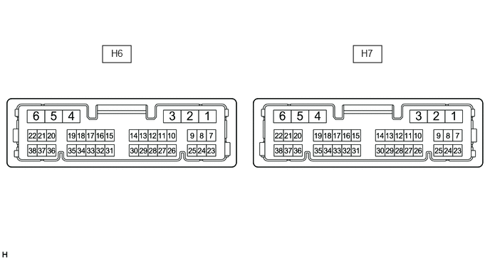
Disconnect the H6 combination meter assembly connectors.
Measure the resistance and voltage according to the value(s) in the table below.
- HINT:
-
Measure the values on the wire harness side with the connector disconnected.
| Terminal No. (Symbol) | Terminal Description | Condition | Specified Condition |
|---|---|---|---|
| H6-22 (B) - Body ground | Auxiliary battery power supply | Ignition switch off | 11 to 14 V |
| H6-38 (IG+) - Body ground | Ignition power supply (IG signal) | Ignition switch off | Below 1 Ω |
| Ignition switch ON | 11 to 14 V | ||
| H6-23 (ES) - Body ground | Ground | Always | Below 1 Ω |
Connect the H6 combination meter assembly connectors.
Measure the resistance and voltage according to the value(s) in the table below.
- HINT:
-
Measure the values on the wire harness side with the connector disconnected.
| Terminal No. (Symbol) | Terminal Description | Condition | Specified Condition |
|---|---|---|---|
| H7-34 (BKL) - Body ground | Driver seat belt buckle switch signal | Driver seat belt fastened | 10 kΩ or higher |
| Driver seat belt unfastened | Below 1 Ω |