P910 HYBRID TRANSMISSION / TRANSAXLE SHIFT LEVER INSTALLATION
PROCEDURE

 1.INSTALL TRANSMISSION FLOOR SHIFT ASSEMBLY
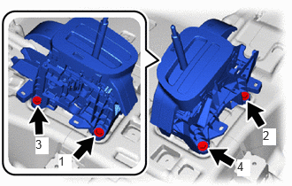
Temporarily install the transmission floor shift assembly to the vehicle body with the 4 bolts.
Fully tighten the 4 bolts in the order shown in the illustration.
- Torque:
- 12 N*m (122 kgf*cm, 9 ft.*lbf)
Engage the 2 clamps to connect the wire harness to the transmission floor shift assembly.
Connect the connector.
Engage the clamp to connect the wire harness to the transmission floor shift assembly.
Connect the shift lock control ECU connector.
33820B
2.CONNECT TRANSMISSION CONTROL CABLE ASSEMBLY
- NOTICE:
-
Before connecting the transmission control cable assembly, check that the shift lever is in N.
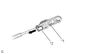
| *1 | Adjuster Case |
| *2 | Adjuster Case Cover |
Slide the adjuster case cover in the direction shown by the arrow.
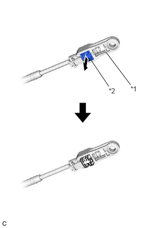
| *1 | Adjuster Case |
| *2 | Lock Piece |
Using a precision screwdriver, pull out the lock piece of the adjuster case.
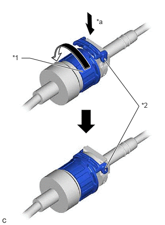
| *1 | Lock Nut |
| *2 | Stopper |
| *a | Push in |
Turn the lock nut of the transmission control cable assembly counterclockwise. While holding the lock nut, push in the stopper.
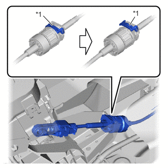
| *1 | Stopper |
Connect the transmission control cable assembly to the transmission floor shift assembly.
- NOTICE:
- ·
After installation, check that the outer part of the stopper is as shown in the illustration.
·Do not forcibly pull the floor shift transmission control select cable into the cabin.
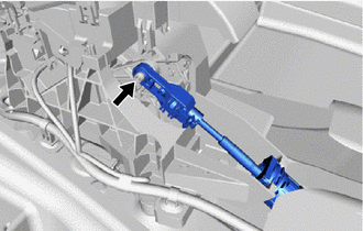
Connect the transmission control cable assembly to the transmission floor shift assembly.
- NOTICE:
- ·
Push the end of the transmission control cable assembly all the way to the base of the transmission floor shift assembly pin.
·Connect the transmission control cable assembly so that the lock piece faces the driver side.
·Before connecting the floor shift transmission control select cable, check that the shift lever is in N.
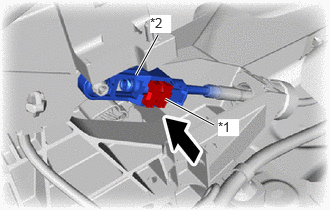
| *1 | Lock Piece |
| *2 | Adjuster Case |
Push in the lock piece of the adjuster case to lock it.
- NOTICE:
-
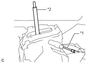 1.271,0.333 1.604,0.333 false 2.333,1.667 2.583,1.167 2.583,1.167 2.75,1.167 true 2.781,1.063 3.094,1.219 0.313,0.156 10 false *1 1.646,0.24 1.958,0.396 0.313,0.156 10 false *2
*1 Transmission Control Cable Assembly *2 Lever Shaft
- ·
When pushing in the lock piece of the adjuster case to lock it, remove your hand from the lever shaft.
·When pushing in the lock piece of the adjuster case to lock it, do not move the lever shaft or transmission control cable assembly forward or backward.
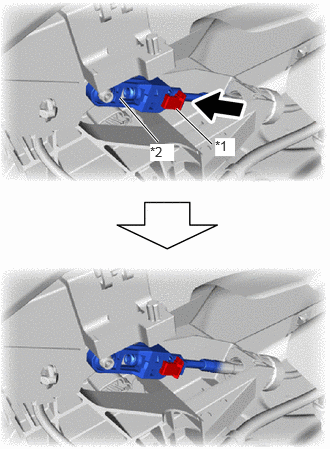
| *1 | Adjuster Case Cover |
| *2 | Adjuster Case |
Move the adjuster case cover in the direction shown by the arrow.
- NOTICE:
-
If the adjuster case cover is not moved far enough so that the adjuster case cover engages the lock piece, the cable will not be able to lock, and reliable shift operation will not be possible.
58910C
3.INSTALL REAR CONSOLE BOX ASSEMBLY
33554
4.INSTALL SHIFT LEVER CAP
Engage the 2 claws to install the shift lever cap to the position indicator housing.
33504F
5.INSTALL SHIFT LEVER KNOB SUB-ASSEMBLY
6.INSPECT SHIFT LEVER POSITION
7.ADJUST SHIFT LEVER POSITION