Home › Engine / Hybrid System › M15A-FKS (ENGINE CONTROL) › RELAY
RM36W0E _51 Engine / Hybrid System _087499 M15A-FKS ENGINE CONTROL _0422191 RELAY G

M15A-FKS ENGINE CONTROL  RELAY  INSPECTION  


PROCEDURE

Hide 85917D 1.INSPECT AIR FUEL RATIO SENSOR HEATER RELAY (A/F HTR)
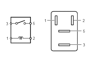
a.
A273391N01
2.667,0.74 2.927,0.74 true 2.531,1.125 2.948,1.125 true 2.531,1.625 2.948,1.625 true 1.708,0.74 1.969,0.74 true 0.229,1.313 0.385,1.51 0.156,0.198 10 1 1.188,1.313 1.344,1.51 0.156,0.198 10 2 0.219,0.781 0.375,0.979 0.156,0.198 10 3 1.188,0.771 1.344,0.969 0.156,0.198 10 5 3,1.052 3.156,1.25 0.156,0.198 10 5 1.604,0.667 1.76,0.865 0.156,0.198 10 1 2.99,0.667 3.146,0.865 0.156,0.198 10 2 3,1.552 3.156,1.75 0.156,0.198 10 3

Measure the resistance according to the value(s) in the table below.

Standard Resistance:
Tester Connection Condition Specified Condition
3 - 5 Auxiliary battery voltage not applied between terminals 1 and 2 10 kΩ or higher
Auxiliary battery voltage applied between terminals 1 and 2 Below 1 Ω


If the result is not as specified, replace the air fuel ratio sensor heater relay (A/F HTR).


Hide 85910E 2.INSPECT INJECTOR RELAY (D INJ)

a.
A273391N01
2.667,0.74 2.927,0.74 true 2.531,1.125 2.948,1.125 true 2.531,1.625 2.948,1.625 true 1.708,0.74 1.969,0.74 true 0.229,1.313 0.385,1.51 0.156,0.198 10 1 1.188,1.313 1.344,1.51 0.156,0.198 10 2 0.219,0.781 0.375,0.979 0.156,0.198 10 3 1.188,0.771 1.344,0.969 0.156,0.198 10 5 3,1.052 3.156,1.25 0.156,0.198 10 5 1.604,0.667 1.76,0.865 0.156,0.198 10 1 2.99,0.667 3.146,0.865 0.156,0.198 10 2 3,1.552 3.156,1.75 0.156,0.198 10 3

Measure the resistance according to the value(s) in the table below.

Standard Resistance:
Tester Connection Condition Specified Condition
3 - 5 Auxiliary battery voltage not applied between terminals 1 and 2 10 kΩ or higher
Auxiliary battery voltage applied between terminals 1 and 2 Below 1 Ω


If the result is not as specified, replace the injector relay (D INJ).


Hide 89561F 3.INSPECT NO.1 ELECTRONIC FUEL INJECTION MAIN RELAY (EFI-MAIN NO. 1)

a.
A273391N01
2.667,0.74 2.927,0.74 true 2.531,1.125 2.948,1.125 true 2.531,1.625 2.948,1.625 true 1.708,0.74 1.969,0.74 true 0.229,1.313 0.385,1.51 0.156,0.198 10 1 1.188,1.313 1.344,1.51 0.156,0.198 10 2 0.219,0.781 0.375,0.979 0.156,0.198 10 3 1.188,0.771 1.344,0.969 0.156,0.198 10 5 3,1.052 3.156,1.25 0.156,0.198 10 5 1.604,0.667 1.76,0.865 0.156,0.198 10 1 2.99,0.667 3.146,0.865 0.156,0.198 10 2 3,1.552 3.156,1.75 0.156,0.198 10 3

Measure the resistance according to the value(s) in the table below.

Standard Resistance:
Tester Connection Condition Specified Condition
3 - 5 Auxiliary battery voltage not applied between terminals 1 and 2 10 kΩ or higher
Auxiliary battery voltage applied between terminals 1 and 2 Below 1 Ω


If the result is not as specified, replace the No.1 electronic fuel injection main relay (EFI-MAIN NO. 1).


Hide 89561G 4.INSPECT NO.2 ELECTRONIC FUEL INJECTION MAIN RELAY (EFI-MAIN NO. 2)

a.
A273391N01
2.667,0.74 2.927,0.74 true 2.531,1.125 2.948,1.125 true 2.531,1.625 2.948,1.625 true 1.708,0.74 1.969,0.74 true 0.229,1.313 0.385,1.51 0.156,0.198 10 1 1.188,1.313 1.344,1.51 0.156,0.198 10 2 0.219,0.781 0.375,0.979 0.156,0.198 10 3 1.188,0.771 1.344,0.969 0.156,0.198 10 5 3,1.052 3.156,1.25 0.156,0.198 10 5 1.604,0.667 1.76,0.865 0.156,0.198 10 1 2.99,0.667 3.146,0.865 0.156,0.198 10 2 3,1.552 3.156,1.75 0.156,0.198 10 3

Measure the resistance according to the value(s) in the table below.

Standard Resistance:
Tester Connection Condition Specified Condition
3 - 5 Auxiliary battery voltage not applied between terminals 1 and 2 10 kΩ or higher
Auxiliary battery voltage applied between terminals 1 and 2 Below 1 Ω


If the result is not as specified, replace the No.2 electronic fuel injection main relay (EFI-MAIN NO. 2).


Hide 89561H 5.INSPECT NO.3 ELECTRONIC FUEL INJECTION MAIN RELAY (EFI-MAIN NO. 3)

a.
A273391N01
2.667,0.74 2.927,0.74 true 2.531,1.125 2.948,1.125 true 2.531,1.625 2.948,1.625 true 1.708,0.74 1.969,0.74 true 0.229,1.313 0.385,1.51 0.156,0.198 10 1 1.188,1.313 1.344,1.51 0.156,0.198 10 2 0.219,0.781 0.375,0.979 0.156,0.198 10 3 1.188,0.771 1.344,0.969 0.156,0.198 10 5 3,1.052 3.156,1.25 0.156,0.198 10 5 1.604,0.667 1.76,0.865 0.156,0.198 10 1 2.99,0.667 3.146,0.865 0.156,0.198 10 2 3,1.552 3.156,1.75 0.156,0.198 10 3

Measure the resistance according to the value(s) in the table below.

Standard Resistance:
Tester Connection Condition Specified Condition
3 - 5 Auxiliary battery voltage not applied between terminals 1 and 2 10 kΩ or higher
Battery voltage applied between terminals 1 and 2 Below 1 Ω


If the result is not as specified, replace the No.3 electronic fuel injection main relay (EFI-MAIN NO. 3).


Hide 28371 6.INSPECT NO.1 IGNITION RELAY (IGP)

a.
A273391N01
2.667,0.74 2.927,0.74 true 2.531,1.125 2.948,1.125 true 2.531,1.625 2.948,1.625 true 1.708,0.74 1.969,0.74 true 0.229,1.313 0.385,1.51 0.156,0.198 10 1 1.188,1.313 1.344,1.51 0.156,0.198 10 2 0.219,0.781 0.375,0.979 0.156,0.198 10 3 1.188,0.771 1.344,0.969 0.156,0.198 10 5 3,1.052 3.156,1.25 0.156,0.198 10 5 1.604,0.667 1.76,0.865 0.156,0.198 10 1 2.99,0.667 3.146,0.865 0.156,0.198 10 2 3,1.552 3.156,1.75 0.156,0.198 10 3

Measure the resistance according to the value(s) in the table below.

Standard Resistance:
Tester Connection Condition Specified Condition
3 - 5 Auxiliary battery voltage not applied between terminals 1 and 2 10 kΩ or higher
Auxiliary battery voltage applied between terminals 1 and 2 Below 1 Ω


If the result is not as specified, replace the No.1 ignition relay (IGP).