RM36W0E
_59
Vehicle Exterior
_088018
WINDOW / GLASS
_0424520
POWER WINDOW MASTER SWITCH
G
WINDOW / GLASS POWER WINDOW MASTER SWITCH INSPECTION
PROCEDURE

 84040
1.INSPECT MULTIPLEX NETWORK MASTER SWITCH ASSEMBLY
a.
1.469,0.188 1.896,0.396
0.427,0.208
0.906,1.875 1.021,1.5
true
1.615,1.885 1.781,1.49
true
2.427,1.875 2.26,1.49
true
0.094,0.115 0.406,0.271
0.313,0.156
10
false
*a
0.813,1.906 1.052,2.063
0.24,0.156
10
false
UP
1.427,1.917 1.958,2.094
0.531,0.177
10
false
DOWN
2.333,1.906 2.667,2.073
0.333,0.167
10
false
GND
1.573,0.219 1.885,0.375
0.313,0.156
10
false
K5
| *a | Component without harness connected
(Multiplex Network Master Switch Assembly) |
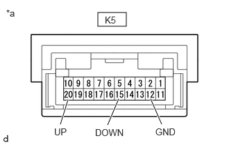
Check the resistance.
i.
Measure the resistance according to the value(s) in the table below.
- Standard Resistance:
Tester Connection Condition Specified Condition K5-20 (UP) - K5-12 (GND) Up position Below 100 Ω K5-15 (DOWN) - K5-12 (GND) Down position Below 100 Ω
If the result is not as specified, replace the multiplex network master switch assembly.
b.
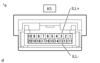
Check that the LED illuminates.
i.
1.5,0.167 1.917,0.417
0.417,0.25
2.115,1.177 2.417,0.292
true
2.115,1.5 2.427,1.927
true
0.094,0.094 0.406,0.25
0.313,0.156
10
false
*a
2.458,0.208 2.813,0.365
0.354,0.156
10
false
ILL+
2.479,1.875 2.833,2.031
0.354,0.156
10
false
ILL-
1.615,0.219 1.969,0.375
0.354,0.156
10
false
K5
| *a | Component without harness connected
(Multiplex Network Master Switch Assembly) |
Apply auxiliary battery voltage to the multiplex network master switch assembly and check that the LEDs illuminate.
- OK:
Battery Connection Specified Condition Auxiliary battery positive (+) → K5-3 (ILL+)
Auxiliary battery negative (-) → K5-13 (ILL-)LEDs illuminate
If the result is not as specified, replace the multiplex network master switch assembly.