CLUTCH CLUTCH UNIT INSPECTION
PROCEDURE

 31250
1.INSPECT CLUTCH DISC ASSEMBLY
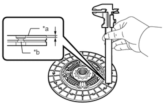
| *a | Facing |
| *b | Rivet |
Using a vernier caliper, measure the rivet head depth.
- Minimum Rivet Head Depth:
0.3 mm (0.0118 in.)
If necessary, replace the clutch disc assembly.
Install the clutch disc assembly to the manual transaxle assembly.
- HINT:
-
Insert the clutch disc assembly in the correct direction.
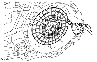
Using a dial indicator, measure the clutch disc assembly runout.
- Maximum Runout:
0.8 mm (0.0315 in.)
If necessary, replace the clutch disc assembly.
31210
2.INSPECT CLUTCH COVER ASSEMBLY
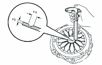
| *a | Width |
| *b | Depth |
Using a vernier caliper, measure the depth and width of the diaphragm spring wear.
- Maximum:
- Depth:
0.5 mm (0.0197 in.)
- Width:
6.0 mm (0.236 in.)
If necessary, replace the clutch cover assembly.
13405
3.INSPECT FLYWHEEL SUB-ASSEMBLY
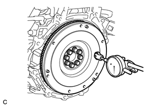
Using a dial indicator, check the flywheel sub-assembly runout.
- Maximum Runout:
0.1 mm (0.00394 in.)
If necessary, replace the flywheel sub-assembly.