HEATING / AIR CONDITIONING AIR CONDITIONING SYSTEM(for Gasoline Model with Manual Air Conditioning System) TERMINALS OF ECU
CHECK AIR CONDITIONING AMPLIFIER ASSEMBLY
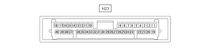
Check air conditioning amplifier assembly.
Disconnect the H23 air conditioning amplifier assembly connector.
Measure the voltage and resistance according to the value(s) in the table below.
| Terminal No.
(Symbol) |
Terminal Description | Condition | Specified Condition |
|---|---|---|---|
| H23-1 (B) - H23-27 (GND) | Power source | Always | 11 to 14 V |
| H23-19 (IG+) - H23-27 (GND) | Power source (IG) | Ignition switch ON | 11 to 14 V |
| Ignition switch off | Below 1 V | ||
| H23-27 (GND) - Body ground | Ground for main power supply | Always | Below 1 Ω |
Connect the H23 air conditioning amplifier assembly connector.
Measure the voltage, resistance and waveform according to the value(s) in the table below.
| Terminal No.
(Symbol) |
Terminal Description | Condition | Specified Condition |
|---|---|---|---|
| H23-4 (LED) - H23-27 (GND) | A/C switch indicator signal | ·
Ignition switch ON ·
A/C switch: On ·
Blower switch: On |
Below 1 V |
·
Ignition switch ON ·
A/C switch: Off ·
Blower switch: On |
11 to 14 V | ||
| H23-6 (AIRF) - H23-27 (GND)*1 | Recirculation/fresh motor signal | ·
Ignition switch ON ·
Air flow mode control switch is set to FACE, FACE/FOOT or DEF: On |
11 to 14 V |
·
Ignition switch ON ·
Air flow mode control switch is set to FOOT or DEF/FOOT: On |
Below 1 V | ||
| H23-7 (AIF) - H23-27 (GND)*1 | Recirculation/fresh motor signal | ·
Ignition switch ON ·
Recirculation/fresh switch: On |
Below 1 V |
·
Ignition switch ON ·
Recirculation/fresh switch: Off |
11 to 14 V | ||
| H23-9 (CANH) - H23-27 (GND) | CAN communication system | Ignition switch ON | Pulse generation |
| H23-11 (S5-3) - H23-27 (GND) | Power supply for air conditioner pressure sensor | Ignition switch ON | 4.75 to 5.25 V |
| Ignition switch off | Below 1 V | ||
| H23-12 (SG-4) - Body ground | Ground for air conditioner pressure sensor | Always | Below 1 Ω |
| H23-13 (TE) - H23-14 (SG-3) | No. 1 cooler thermistor signal | ·
Ignition switch ON ·
Evaporator temperature: 0°C (32°F) |
1.7 to 2.1 V |
·
Ignition switch ON ·
Evaporator temperature: 15°C (59°F) |
0.9 to 1.3 V | ||
| H23-14 (SG-3) - Body ground | Ground for No. 1 cooler thermistor | Always | Below 1 Ω |
| H23-15 (SBLW) - H23-27 (GND) | Blower motor operation condition signal | ·
Ignition switch ON ·
Blower switch: On |
Below 1 V |
·
Ignition switch ON ·
Blower switch: Off |
11 to 14 V | ||
| H23-17 (DEF) - H23-27 (GND) | Defogger sensing signal | ·
Ignition switch ON ·
Airflow mode control switch is set to DEF/FOOT or DEF: On |
11 to 14 V |
·
Ignition switch ON ·
Airflow mode control switch is set to FACE, FACE/FOOT or FOOT: Off |
Below 1 V | ||
| H23-20 (SOL+) - H23-27 (GND) | Compressor solenoid operation signal | ·
Engine running ·
Blower switch: On ·
A/C switch: On |
Pulse generation
(See waveform 1) |
| H23-21 (HR) - H23-27 (GND) | Heater relay operation signal | ·
Ignition switch ON ·
Blower switch: LO |
Below 1 V |
·
Ignition switch ON ·
Blower switch: Off |
11 to 14 V | ||
| H23-22 (LREC) - H23-27 (GND)*1 | Recirculation/fresh switch indicator signal | ·
Ignition switch ON ·
Recirculation/fresh switch: On |
Below 1 V |
·
Ignition switch ON ·
Recirculation/fresh switch: Off |
11 to 14 V | ||
| H23-23 (AIR) - H23-27 (GND)*1 | Recirculation/fresh motor signal | ·
Ignition switch ON ·
Recirculation/fresh switch: On |
Below 1 V |
·
Ignition switch ON ·
Recirculation/fresh switch: Off |
11 to 14 V | ||
| H23-26 (CANL) - H23-27 (GND) | CAN communication system | Ignition switch ON | Pulse generation |
| H23-30 (HEAT) - H23-27 (GND) | Max hot sensing signal | ·
Ignition switch ON ·
MAX HOT position |
11 to 14 V |
·
Ignition switch ON ·
Other than MAX HOT position |
Below 1 V | ||
| H23-31 (COOL) - H23-27 (GND)*2 | Max cool sensing signal | ·
Ignition switch ON ·
MAX COOL position |
11 to 14 V |
·
Ignition switch ON ·
Other than MAX COOL position |
Below 1 V | ||
| H23-32 (A/C) - H23-27 (GND) | A/C switch signal | ·
Ignition switch ON ·
A/C switch: On |
11 to 14 V |
·
Ignition switch ON ·
A/C switch: Off |
Below 1 V | ||
| H23-33 (FR) - H23-27 (GND)*1 | Recirculation/fresh switch signal | ·
Ignition switch ON ·
Recirculation/fresh switch: On |
11 to 14 V |
·
Ignition switch ON ·
Recirculation/fresh switch: Off |
Below 1 V | ||
| H23-36 (PRE) - H23-27 (GND) | Air conditioner pressure sensor signal | ·
Ignition switch ON ·
Air conditioning system operating ·
Refrigerant pressure: Normal pressure (less than 3.025 MPaG [30.8 kgf/cm2, 439 psi]) and 0.176 MPaG [1.8 kgf/cm2, 26 psi] or higher) |
Less than 4.73 V and 0.62 V or higher*3 |
·
Ignition switch ON ·
Air conditioning system operating ·
Refrigerant pressure: Abnormal pressure (3.025 MPaG [30.8 kgf/cm2, 439 psi] or higher) |
4.73 V or higher*3 | ||
·
Ignition switch ON ·
Air conditioning system operating ·
Refrigerant pressure: Abnormal pressure (less than 0.176 MPaG [1.8 kgf/cm2, 26 psi]) |
Less than 0.62 V*3 | ||
| H23-39 (F/D) - H23-27 (GND)*1 | Recirculation/fresh double layer sensing signal | ·
Ignition switch ON ·
Airflow mode control switch is set to FOOT or DEF/FOOT: On |
11 to 14 V |
·
Ignition switch ON ·
Airflow mode control switch is set to FACE, FACE/FOOT or DEF: On |
Below 1 V |
*1: for Double Layer Type
*2: for M15A-FKS
*3: While sensor voltage is 5 V.
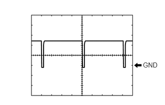
Waveform 1:
| Item | Content |
|---|---|
| Terminal No. | H23-20 (SOL+) - H23-27 (GND) |
| Tool Setting | 5 V/DIV., 500 μs./DIV. |
| Condition | ·
Engine running ·
Blower switch: On ·
A/C switch: On |
NO. 2 SEMICONDUCTOR POWER INTEGRATION ECU (w/ PTC Heater)

Check No. 2 semiconductor power integration ECU.
Disconnect No. 2 semiconductor power integration ECU connector.
Measure the voltage, resistance and waveform according to the value(s) in the table below.
- Standard:
Terminal No.
(Symbol)Terminal Description Condition Specified Condition A87-1 (+B) - Body ground Power source Always 8 to 14 V A88-1 (L) - Body ground Quick heater assembly (PTC1) ·Ignition switch ON
·Quick heater assembly (PTC1) off
Below 3 V ·Ignition switch ON
·Quick heater assembly (PTC1) on
8 V or higher A88-2 (L) - Body ground Quick heater assembly (PTC2) ·Ignition switch ON
·Quick heater assembly (PTC2) off
Below 3 V ·Ignition switch ON
·Quick heater assembly (PTC2) on
8 V or higher A88-7 (CXPI) - Body ground CXPI communication system Ignition switch ON Pulse generation A88-9 (IG) - Body ground Power source (IG) Ignition switch off Below 1.5 V Ignition switch ON 8 to 14 V A88-13 (GND1) - Body ground Ground for No. 2 semiconductor power integration ECU Always Below 1 Ω A88-16 (L) - Body ground Quick heater assembly (PTC3) ·Ignition switch ON
·Quick heater assembly (PTC3) off
Below 3 V ·Ignition switch ON
·Quick heater assembly (PTC3) on
8 V or higher