STOP AND START STOP AND START SYSTEM P085011 Park/Neutral Switch Circuit Short to Ground P085015 Park/Neutral Switch Circuit Short to Battery or Open
DESCRIPTION
-
The engine stop and start ECU detects a malfunction by comparing the shift position signal with the neutral position switch signal input state. If a malfunction is detected, the engine stop and start ECU blinks the stop and start cancel indicator light, prohibits the stop and start control and stores DTC P085011 or P085015.
| DTC No. | Detection Item | DTC Detection Condition | Trouble Area | Warning Indicate | Memory | Note |
|---|---|---|---|---|---|---|
| P085011 | Park/Neutral Switch Circuit Short to Ground | The following condition continues for 1 second or more (1 trip detection logic)
·
Short in neutral position switch circuit. |
·
Neutral position switch ·
Engine stop and start ECU ·
ECM ·
Wire harness or connector |
Blinking | DTC stored | SAE Code: P0851 |
| P085015 | Park/Neutral Switch Circuit Short to Battery or Open | The following condition continues for 1 second or more (1 trip detection logic)
·
Open or short in neutral position switch circuit. |
·
Neutral position switch ·
Engine stop and start ECU ·
ECM ·
Wire harness or connector |
Blinking | DTC stored | SAE Code: P0852 |
WIRING DIAGRAM
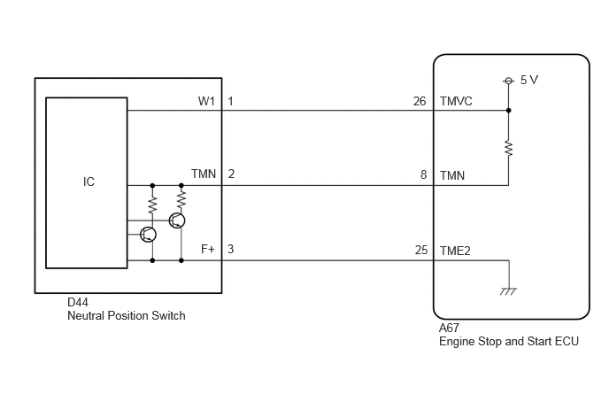
CAUTION / NOTICE / HINT
- NOTICE:
- ·
Before replacing the engine stop and start ECU, read the number of starter operations and write it into a new engine stop and start ECU.
Click hereEngine / Hybrid System>STOP AND START>STOP AND START SYSTEM>REGISTRATION
·After replacing the engine stop and start ECU, perform learning of the external backup boost converter (eco run vehicle converter assembly).
Click hereEngine / Hybrid System>STOP AND START>STOP AND START SYSTEM>REGISTRATION
·After replacing the engine stop and start ECU or air conditioning amplifier assembly, reset and perform learning of the air conditioning information in the engine stop and start ECU.
Click hereEngine / Hybrid System>STOP AND START>STOP AND START SYSTEM>REGISTRATION
·When the ECM is replaced on a vehicle with a non-specified auxiliary battery, it is necessary to perform auxiliary battery type switching.
Click hereEngine / Hybrid System>STOP AND START>STOP AND START SYSTEM>REGISTRATION
·Inspect the fuses for circuits related to this system before performing the following procedure.
- HINT:
- ·
Using the GTS, read the freeze frame data before troubleshooting. System condition information is recorded as freeze frame data the moment a DTC is stored. This information can be useful when troubleshooting.
Click hereEngine / Hybrid System>STOP AND START>STOP AND START SYSTEM>FREEZE FRAME DATA
·For wire harness and connector inspection procedures and precautions, refer toGeneral>INTRODUCTION>HOW TO TROUBLESHOOT ECU CONTROLLED SYSTEMS>HOW TO PROCEED WITH TROUBLESHOOTING
·DTCs for the stop and start system are not cleared even if the malfunction has been repaired. After repairing the malfunction, be sure to clear the DTCs.
Click hereEngine / Hybrid System>STOP AND START>STOP AND START SYSTEM>DTC CHECK / CLEAR
PROCEDURE
Enter the following menus: Powertrain / Stop and Start / Data List / Neutral Switch.
- Powertrain > Stop and Start > Data List
-
Tester Display Neutral Switch - 50003 392 202
Read the value when the shift lever is in neutral and any other position.
- OK:
Tester Display Condition Normal Condition Neutral Switch Shift lever in neutral ON Neutral Switch Shift lever in any position other than neutral OFF
- Result:
Proceed to OK NG
OK
Click hereGeneral>INTRODUCTION>HOW TO TROUBLESHOOT ECU CONTROLLED SYSTEMS>HOW TO PROCEED WITH TROUBLESHOOTING
NG
Disconnect the A67 engine stop and start ECU connector.
Disconnect the D44 neutral position switch connector.
Measure the resistance according to the value(s) in the table below.
- Standard Resistance:
Tester Connection Condition Specified Condition A67-26 (TMVC) - D44-1 (W1) Always Below 1 Ω A67-25 (TME2) - D44-3 (F+) Always Below 1 Ω A67-8 (TMN) - D44-2 (TMN) Always Below 1 Ω A67-26 (TMVC) - Body ground and other terminals Always 10 kΩ or higher D44-1 (W1) - Body ground and other terminals Always 10 kΩ or higher A67-25 (TME2) - Body ground and other terminals Always 10 kΩ or higher D44-3 (F+) - Body ground and other terminals Always 10 kΩ or higher A67-8 (TMN) - Body ground and other terminals Always 10 kΩ or higher D44-2 (TMN) - Body ground and other terminals Always 10 kΩ or higher
- Result:
Proceed to OK NG
OK
NG
Measure the voltage according to the value(s) in the table below.
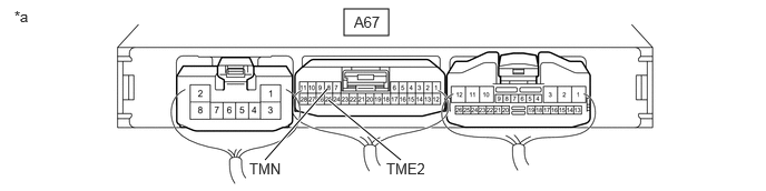
| *a | Component with harness connected
(Engine Stop and Start ECU) |
- | - |
- Standard Voltage:
Tester Connection Condition Specified Condition A67-8 (TMN) - A67-25 (TME2) Ignition switch ON, shift lever in neutral 2.7 to 4.3 V A67-8 (TMN) - A67-25 (TME2) Ignition switch ON, shift lever in any position other than neutral 0.7 to 1.9 V
- Result:
Result OK NG
OK
NG