LIGHTING (EXT) LIGHTING SYSTEM Back-up Light Circuit
DESCRIPTION
The hybrid vehicle control ECU controls the back-up lights via the BKUP LP relay.
WIRING DIAGRAM
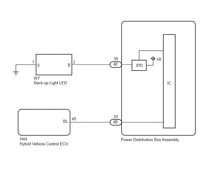
CAUTION / NOTICE / HINT
- NOTICE:
- ·
Before replacing the hybrid vehicle control ECU, refer to Service Bulletin.*1
*1: w/ Entry and Start System
PROCEDURE
Turn the ignition switch to ON.
Changes the shift lever R position.
Using the GTS, read the Data List.
- Body Electrical > Power Distribution Box > Data List
-
Tester Display Measurement Item Range Normal Condition Diagnostic Note Back-up Light Fuse Shut Off Status Back-up light fuse condition OFF or ON OFF: Back-up light fuse not shut off
ON: Back-up light fuse shut off-
- Body Electrical > Power Distribution Box > Data List
-
Tester Display Back-up Light Fuse Shut Off Status - 50003 475 1308
- OK:
The Data List value displays "OFF".
- Result:
Proceed to OK NG
OK
NG
Enter the following menus: Body Electrical > Power Distribution Box > Data List.
Using the GTS, read the Data List.
- Body Electrical > Power Distribution Box > Data List
-
Tester Display Measurement Item Range Normal Condition Diagnostic Note Back-up Light Input Signal Back-up light input OFF or ON OFF: Back-up light is not input
ON: Back-up light is input-
- Body Electrical > Power Distribution Box > Data List
-
Tester Display Back-up Light Input Signal - 50003 475 1305
- OK:
Display changes according to shift lever operation.
- Result:
Proceed to OK NG
OK
NG
Enter the following menus: Body Electrical > Power Distribution Box > Data List.
Using the GTS, read the Data List.
- Body Electrical > Power Distribution Box > Data List
-
Tester Display Measurement Item Range Normal Condition Diagnostic Note Back-up Light Output Signal Back-up light output OFF or ON OFF: Back-up light is not output
ON: Back-up light is output-
- Body Electrical > Power Distribution Box > Data List
-
Tester Display Back-up Light Output Signal - 50003 475 1306
- OK:
Display changes according to shift lever operation.
- Result:
Proceed to OK NG
OK
NG
for LHD:
Click herePower Source / Network>POWER DISTRIBUTION>MAIN BODY ECU (for LHD)>REMOVAL
for RHD:
Click herePower Source / Network>POWER DISTRIBUTION>MAIN BODY ECU (for RHD)>REMOVAL
Disconnect the W7 back-up light LED connector.
Disconnect the cable from the negative (-) auxiliary battery terminal.
Disconnect the 4E power distribution box assembly connector.
Measure the resistance according to the value(s) in the table below.
- Standard Resistance:
Tester Connection Condition Specified Condition W7-2 (B) or 4E-38 - Body ground Always 10 kΩ or higher
- Result:
Proceed to OK NG
OK
for LHD:
Click herePower Source / Network>POWER DISTRIBUTION>MAIN BODY ECU (for LHD)>REMOVAL
for RHD:
Click herePower Source / Network>POWER DISTRIBUTION>MAIN BODY ECU (for RHD)>REMOVAL
NG
Measure the voltage according to the value(s) in the table below.
- Standard Voltage:
Tester Connection Condition Specified Condition 4B-29 - Body ground Ignition switch ON, shift lever except R position Below 1 V 4B-29 - Body ground Ignition switch ON, shift lever R position 11 to 14 V
- Result:
Proceed to OK NG
OK
for LHD:
Click herePower Source / Network>POWER DISTRIBUTION>MAIN BODY ECU (for LHD)>REMOVAL
for RHD:
Click herePower Source / Network>POWER DISTRIBUTION>MAIN BODY ECU (for RHD)>REMOVAL
NG
Disconnect the H44 hybrid vehicle control ECU connector.
Disconnect the 4B power distribution box assembly connector.
Measure the resistance according to the value(s) in the table below.
- Standard Resistance:
Tester Connection Condition Specified Condition H44-49 (BL) - 4B-29 Always Below 1 Ω H44-49 (BL) or 4B-29 - Body ground Always 10 kΩ or higher
- Result:
Proceed to OK NG
OK
NG
Disconnect the W7 back-up light LED connector.
Turn the ignition switch to ON.
Changes the shift lever except R position.
Changes the shift lever R position.
Using the GTS, read the Data List.
- Body Electrical > Power Distribution Box > Data List
-
Tester Display Measurement Item Range Normal Condition Diagnostic Note Back-up Light Fuse Shut Off Status Back-up light fuse condition OFF or ON OFF: Back-up light fuse not shut off
ON: Back-up light fuse shut off-
- Body Electrical > Power Distribution Box > Data List
-
Tester Display Back-up Light Fuse Shut Off Status - 50003 475 1308
- OK:
The Data List value displays "OFF".
- Result:
Proceed to OK NG
OK
NG
Disconnect the W7 back-up light LED connector.
Disconnect the cable from the negative (-) auxiliary battery terminal.
Disconnect the 4E power distribution box assembly connector.
Measure the resistance according to the value(s) in the table below.
- Standard Resistance:
Tester Connection Condition Specified Condition W7-2 (B) or 4E-38 - Body ground Always 10 kΩ or higher
- Result:
Proceed to OK NG
OK
for LHD:
Click herePower Source / Network>POWER DISTRIBUTION>MAIN BODY ECU (for LHD)>REMOVAL
for RHD:
Click herePower Source / Network>POWER DISTRIBUTION>MAIN BODY ECU (for RHD)>REMOVAL
NG