1KR-FE STARTING STARTER(w/ Stop And Start System) REASSEMBLY
PROCEDURE

 28011
1.INSTALL STARTER CLUTCH SUB-ASSEMBLY
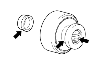

|
High-temperature Grease |
Apply high-temperature grease to the bushing and spline of the starter clutch sub-assembly and stop collar.
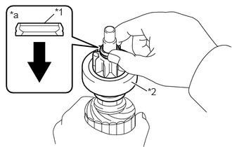
| *1 | Stop Collar |
| *2 | Starter Clutch Sub-assembly |
| *a | Cross Section Drawing |
|
|
Starter Clutch Sub-assembly Side |
Place the starter clutch sub-assembly and stop collar to the starter armature assembly.
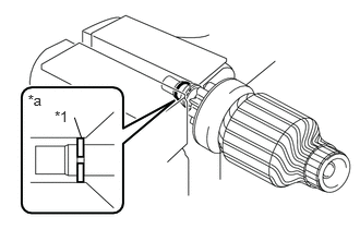
| *1 | Snap Ring |
| *a | Cross Section Drawing |
Apply high-temperature grease to a new snap ring, and install it to the groove of the starter armature assembly.
Using a vise between aluminum plates, compress the snap ring.
- NOTICE:
-
Do not overtighten the vise.
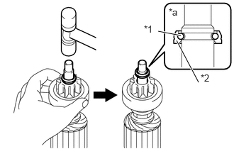
| *1 | Snap Ring |
| *2 | Stop Collar |
| *a | Cross Section Drawing |
Using a plastic-faced hammer, while holding the starter clutch sub-assembly, tap the starter armature assembly and engage the stop collar to the snap ring.
- NOTICE:
-
Do not tap the starter armature assembly too strongly.
28160
2.INSTALL STARTER ARMATURE ASSEMBLY
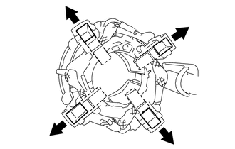
|
|
Push Out |
As shown in the illustration, push out the 4 brushes of the starter yoke assembly towards the outer side and them there.
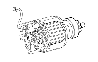
Install the starter armature assembly to the starter yoke assembly.
Secure the starter armature assembly shaft in a vise between aluminum plates.
- NOTICE:
-
Do not overtighten the vise.
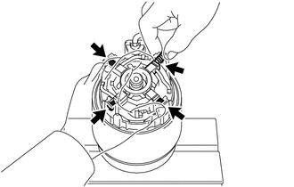
Install the 4 brush springs.
- NOTICE:
-
Make sure the brush spring does not fly out.
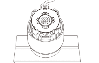
Install the brush holder insulator to the brush holder of the starter yoke assembly.
28130
3.INSTALL STARTER COMMUTATOR END FRAME ASSEMBLY
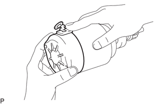
Install the starter commutator end frame to the starter yoke assembly.
- NOTICE:
-
While holding down the lead wire, install the starter commutator end frame assembly.
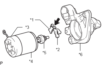
| *1 | Rubber Seal |
| *2 | Starter Pinion Drive Lever |
| *3 | Starter Commutator End Frame Assembly |
| *4 | Starter Yoke Assembly |
| *5 | Starter Clutch Sub-assembly |
| *6 | Starter Drive Housing Assembly |
|
|
High-temperature Grease |
Apply high-temperature grease to the parts of the starter pinion drive lever that contact the magnet starter switch assembly, starter clutch sub-assembly and starter drive housing assembly.
Install the starter pinion drive lever to the starter clutch sub-assembly.
Install the starter commutator end frame assembly together with starter yoke assembly, starter pinion drive lever and rubber seal to the starter drive housing assembly.
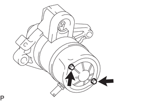
Install the 2 through bolts.
- Torque:
- 6.4 N*m (65 kgf*cm, 57 in.*lbf)
28150
4.INSTALL MAGNET STARTER SWITCH ASSEMBLY
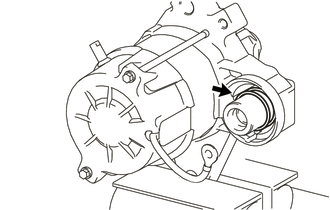
Install the return spring to the starter pinion drive lever.
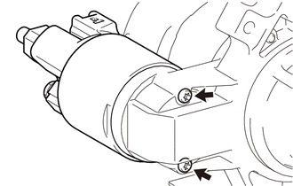
Using "TORX" socket wrench T20, install the magnet starter switch assembly to the starter drive housing assembly with the 2 bolts.
- Torque:
- 3.8 N*m (39 kgf*cm, 34 in.*lbf)
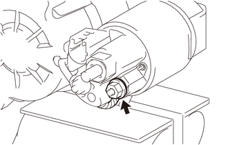
Install the wire harness to the terminal 45 with the nut.
- Torque:
- 8.0 N*m (82 kgf*cm, 71 in.*lbf)