NETWORKING NETWORK GATEWAY ECU(for RHD) REMOVAL
CAUTION / NOTICE / HINT
The necessary procedures (adjustment, calibration, initialization, or registration) that must be performed after parts are removed, installed, or replaced during the horn button assembly removal/installation are shown below.
| Replacement Part or Procedure | Necessary Procedures | Effects/Inoperative when not performed | Link |
|---|---|---|---|
| Disconnect cable from negative auxiliary battery terminal | Memorize steering angle neutral point | Parking assist monitor system | ( ) |
| Central gateway ECU (network gateway ECU) | Update ECU security key | - | ()
|
- HINT:
-
When the cable is disconnected / reconnected to the auxiliary battery terminal, systems temporarily stop operating. However, each system has a function that completes learning the first time the system is used.
- ·
Learning completes when vehicle is driven
Effect/Inoperative Function When Necessary Procedures are not Performed Necessary Procedures Link *1: for Gasoline Model
Lane tracing assist system Drive the vehicle straight ahead at 35 km/h (22 mph) or more for 5 second or more. ( )
Pre-collision system Stop and start system *1 Drive the vehicle until stop and start control is permitted (approximately 5 to 60 minutes) ( )
·Learning completes when vehicle is operated normally
Effect/Inoperative Function When Necessary Procedures are not Performed Necessary Procedures Link Power door lock control system
·Back door opener
Perform door unlock operation with door control switch or electrical key transmitter sub-assembly switch. ( )
Air conditioning system After the ignition switch is turned to ON, the servo motor standard position is recognized. -
PROCEDURE

 1.REMOVE INSTRUMENT PANEL JUNCTION BLOCK ASSEMBLY WITH MULTIPLEX NETWORK BODY ECU
82878
2.REMOVE ECU INTEGRATION BOX LH
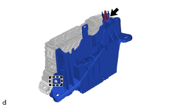
Remove the bolt.
Disengage the clamp.
Remove the ECU integration box LH from the instrument panel junction block assembly.
89111
3.REMOVE CENTRAL GATEWAY ECU (NETWORK GATEWAY ECU)
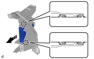

|
Remove in this Direction |
Disengage the claws to remove the central gateway ECU (network gateway ECU) as shown in the illustration.
- NOTICE:
- ·
If the ECU integration box LH is deformed or damaged, replace it.
·Do not bend the claws more than necessary.