RM36W0E
_56
Audio / Visual / Telematics
_091907
TELEMATICS
_0437788
MAYDAY SWITCH
G
TELEMATICS MAYDAY SWITCH INSPECTION
PROCEDURE

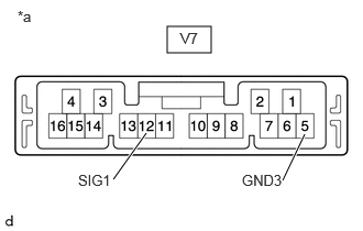
 1.INSPECT MAYDAY SWITCH ASSEMBLY
a.
1.583,0.25 2,0.5
0.417,0.25
2.885,1.271 2.677,1.708
true
1.385,1.26 1.073,1.698
true
2.292,1.625 2.875,1.875
0.583,0.25
10
false
GND3
0.74,1.625 1.323,1.875
0.583,0.25
10
false
SIG1
1.708,0.281 2.021,0.479
0.313,0.198
10
false
V7
0.167,0.073 0.479,0.271
0.313,0.198
10
false
*a
| *a | Component without harness connected
(Mayday Switch Assembly) |
Check the resistance.
i.
Measure the resistance according to the value(s) in the table below.
- Standard Resistance:
Tester Connection Condition Specified Condition V7-12(SIG1) - V7-5(GND3) Mayday switch is pushed 81.1 Ω - 82.8 Ω V7-12(SIG1) - V7-5(GND3) Mayday switch is not pushed 407.8 Ω - 416.1 Ω
If the result is not as specified, replace the mayday switch assembly.