INTERIOR PANELS / TRIM REAR CONSOLE BOX INSTALLATION
PROCEDURE

 58910C
1.INSTALL REAR CONSOLE BOX ASSEMBLY
Engage the claws and guides to install the rear console box assembly as shown in the illustration.
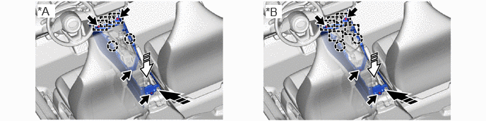
| *A | for Manual Transaxle | *B | for CVT |

|
Install in this Direction (1) | 
|
Install in this Direction (2) |
Install the 2 bolts.
Install the 2 screws.
58822A
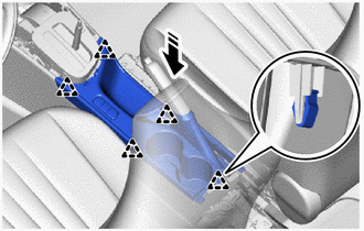
2.INSTALL REAR UPPER CONSOLE PANEL
Engage the clamp.
Connect the connector.
|
|
Install in this Direction |
Engage the clips to install the rear upper console panel as shown in the illustration.
58857A
3.INSTALL UPPER NO. 1 CONSOLE SUPPORT BRACKET (for HV Model TMMF Made)
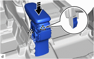
Engage the 2 clips to install the concole rear end panel sub-assembly as shown in the illustration.
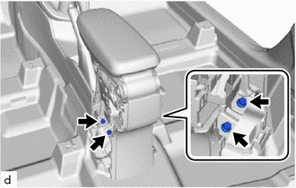
Install the 4 bolts.
- Torque:
- 25 N*m (255 kgf*cm, 18 ft.*lbf)
58912C
4.INSTALL NO. 2 BOX SIDE PANEL (for HV Model TMMF Made)
- HINT:
-
Use the same procedure as for the No. 1 side.
58911A
5.INSTALL NO. 1 BOX SIDE PANEL (for HV Model TMMF Made)
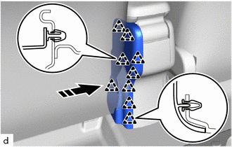
Engage the 9 clips to install the No. 2 box side panel as shown in the illustration.
58903A
6.INSTALL CONSOLE REAR END PANEL SUB-ASSEMBLY (for Gasoline Model TMMF Made)
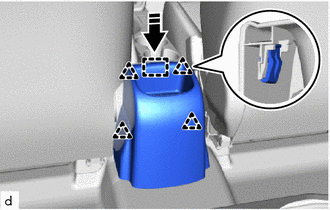
Engage the 4 clips to install the console rear end panel sub-assembly.
58818A
7.INSTALL CONSOLE BOX FRONT COVER (for TMC Made)
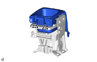
Engage the clips to install the console box front cover.
Install the 2 screws.
58857A
8.INSTALL UPPER NO. 1 CONSOLE SUPPORT BRACKET (for TMC Made)
|
|
Install in this Direction |
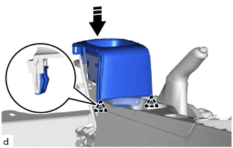
Engage the clips to install the upper No. 1 console support bracket with console box front cover as shown in the illustration.
Install the 4 bolts.
- Torque:
- 25 N*m (255 kgf*cm, 18 ft.*lbf)
58903A
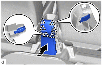
9.INSTALL CONSOLE REAR END PANEL SUB-ASSEMBLY (for TMC Made)
|
|
Install in this Direction |
Engage the clips to install the console rear end panel sub-assembly as shown in the illustration.
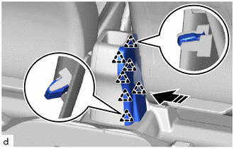
10.INSTALL NO. 1 BOX SIDE PANEL (for TMC Made)
|
|
Install in this Direction |
Engage the clips to install the No. 1 box side panel as shown in the illustration.
58912C
11.INSTALL NO. 2 BOX SIDE PANEL (for TMC Made)
- HINT:
-
Use the same procedure as for the No. 1 side.
58802E
12.INSTALL FRONT CONSOLE BOX SUB-ASSEMBLY
Connect the connector.
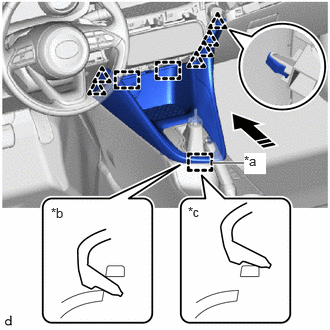
| *a | Guide (A) |
| *b | Correct |
| *c | Incorrect |
|
|
Install in this Direction |
While inserting guide (A) as shown in the illustration, engage the clips and guides to temporarily install the front console box sub-assembly as shown in the illustration.
To avoid damaging the front console box sub-assembly, make sure that the guide (A) is securely and correctly engaged.
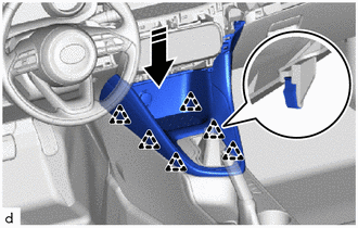

|
Install in this Direction |
Engage the clips as shown in the illustration.
33554
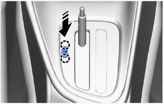
13.INSTALL SHIFT LEVER CAP (for CVT)
|
|
Install in this Direction |
Engage the 2 claws to install the shift lever cap to the position indicator housing.
33504F
14.INSTALL SHIFT LEVER KNOB SUB-ASSEMBLY (for CVT)
33504F
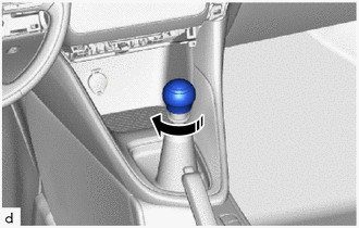
15.INSTALL SHIFT LEVER KNOB SUB-ASSEMBLY (for Manual Transaxle)
|
|
Install in this Direction |
Turn the shift lever knob sub-assembly as shown in the illustration and install it.
55407B
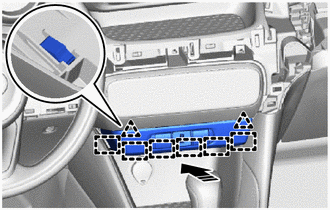
16.INSTALL SWITCH HOLE BASE SUB-ASSEMBLY
Connect each connector.
|
|
Install in this Direction |
Engage the guides and clips to install the switch hole base sub-assembly as shown in the illustration.
55432B
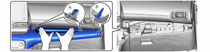
17.INSTALL LOWER INSTRUMENT PANEL FINISH PANEL
w/ Entry and Start System:
Connect the connector.
First align clip A, then align guide B.
- HINT:
- ·
Do not engage the clips.
·Make sure the clips do not move out of position.
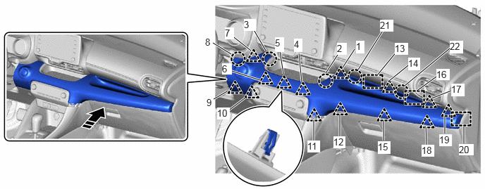
While holding the parts in place so that clip A do not move out of position, engage the guides and press the clips and claws in the order shown in the illustration to install the lower instrument panel finish panel.
|
|
Install in this Direction | - | - |
- HINT:
-
Check that the lower instrument panel finish panel is securely installed and that none of the clips and claws are raised up or not properly engaged.
55479D
18.INSTALL LOWER INSTRUMENT CLUSTER FINISH PANEL GARNISH
Engage the guide and claw to install the lower instrument cluster finish panel garnish.