RM36W0E
_58
Vehicle Interior
_087985
METER / GAUGE / DISPLAY
_0420292
METER / GAUGE SYSTEM
U
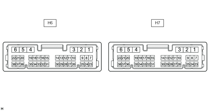
METER / GAUGE / DISPLAY METER / GAUGE SYSTEM TERMINALS OF ECU
COMBINATION METER ASSEMBLY
1.5,0.667 1.917,0.917
0.417,0.25
5.167,0.667 5.583,0.917
0.417,0.25
1.625,0.698 2.083,0.896
0.458,0.198
10
false
H6
5.292,0.698 5.75,0.896
0.458,0.198
10
false
H7
a.
Measure the voltage and resistance and check for pulses according to the value(s) in the table below.
| Terminal No. (Symbol) | Terminal Description | Condition | Specified Condition |
|---|---|---|---|
| H6-1 (B) - Body ground | Auxiliary battery | Ignition switch off | 11 to 14 V |
| H6-9 (CANH) | CAN communication line | - | - |
| H6-10 (MSCL) | Local bus communication line | - | - |
| H6-11 (TX1-) - Body ground | Outside temperature sensor signal | - | - |
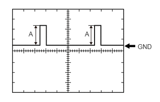
| H6-13 (FR2) - H6-24 (FE&B)*7 | Fuel level signal | Ignition switch ON, fuel level full → low (fuel level warning light on) | Pulse generation
(See waveform 3) |
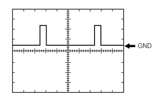
| H6-14 (FV) - Body ground | Fuel sender gauge (Power source) | Ignition switch ON | Pulse generation
(See waveform 1) |
| H6-15 (MSTI) - Body ground | Steering pad switch signal | Ignition switch ON, up, down, right and left switches on steering pad switch not pushed | 4.8 to 5.2 V |
| H6-16 (TX1+) - Body ground | Outside temperature sensor signal | - | - |
| H6-19 (EP) - Body ground | Ground | Always | Below 1 Ω |
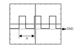
| H6-20 (SI) - Body ground | Speed signal for other system (Input) | Ignition switch ON, wheel being rotated | Pulse generation
(See waveform 2) |
| H6-22 (B) - Body ground | Auxiliary battery | Ignition switch off | 11 to 14 V |
| H6-23 (ES) - Body ground | Ground | Always | Below 1 Ω |
| H6-24 (FE&B) -Body ground | Fuel sender gauge (Ground) | Always | Below 1 Ω |
| H6-25 (CANL) | CAN communication line | - | - |
| H6-27 (MSCH) | Local bus communication line | - | - |
| H6-31 (FR) - H6-24 (FE&B) | Fuel level signal | Ignition switch ON, fuel level full → low (fuel level warning light on) | Pulse generation
(See waveform 3) |
| H6-32 (MSM+) - Body ground | Steering pad switch signal | Ignition switch On, OK and back switches on steering pad switch not pushed | 4.8 to 5.2 V |
| H6-35 (A) - Body ground*6 | Steering vibration signal | Ignition switch ON, steering vibration off → ON | Below 1 V → 11 to 14 V |
| H6-36 (+S) - Body ground | Speed signal for other systems (Output) | Ignition switch ON, wheel being rotated | Pulse generation
(See waveform 2) |
| H6-38 (IG+) - Body ground | Ignition switch signal | Ignition switch off | Below 1 V |
| Ignition switch ON | 11 to 14 V*3
10.5 to 16 V*4 |
||
| H7-1 (LL) - Body ground | LH turn signal | LH turn indicator light off → blinking | Below 1 V → 11 to 14 V ←→ Below 1 V |
| H7-2 (LR) - Body ground | RH turn signal | RH turn indicator light off → blinking | Below 1 V → 11 to 14 V ←→ Below 1 V |
| H7-5 (TRNL) - Body ground | LH turn signal | LH turn indicator light off → blinking | Below 1 V → 11 to 14 V ←→ Below 1 V |
| H7-6 (TRNR) - Body ground | RH turn signal | RH turn indicator light off → blinking | Below 1 V → 11 to 14 V ←→ Below 1 V |
| H7-7 (LP) - Body ground | Security indicator signal | Security indicator light off → blinking | Below 2 V → Pulse generation |
| H7-16 (SW) - Body ground*1 | Brake fluid level signal | Ignition switch ON, brake fluid level not low (brake warning light off) → low (brake warning light on) | 11 to 14 V → Below 1 V |
| H7-17 (HAZ) - Body ground | Hazard warning signal switch signal | Hazard warning signal switch off → on | 11 to 14 V → Below 1 V |
| H7-23 (S) - Body ground*5 | Engine oil pressure signal | Engine started → not started | 11 to 14 V → Below 1 V |
| H7-31 (OILW) - Body ground | Engine oil level signal | Ignition switch ON, engine oil level not low → low | Below 1 V → 11 to 14 V |
| H7-32 (VCM) - Body ground*2 | Vacuum warning switch signal | Engine started, vacuum warning switch off (brake warning light off) → on (brake warning light on) | 11 to 14 V → Below 1 V |
| H7-34 (BKL) - Body ground | Front passenger seat belt warning signal | Ignition switch ON, front passenger seat belt unfastened → fastened | Below 1 V → 11 to 14 V |
*1: w/ Level Warning Switch
*2: for M15A-FKS
*3: w/o Stop and Start System
*4: w/ Stop and Start System
*5: for 1KR-FE
*6: w/ Toyota Safety Sense
*7: for Gasoline Model AWD
2.958,0.896 3.417,1.094
0.458,0.198
10
false
GND
| Item | Condition |
|---|---|
| Tester connection | H6-14 (FV) - Body ground |
| Tool setting | 2.5 V/DIV., 20 ms./DIV. |
| Condition | Ignition switch ON |
| Specified Condition | 4.5 to 5.5 V |
2.969,1.198 3.323,1.396
0.354,0.198
10
false
GND
1.156,1.625 1.365,1.833
0.208,0.208
10
false
A
| Item | Condition |
|---|---|
| Tester connection | ·
H6-20 (SI) - Body ground ·
H6-36 (+S) - Body ground |
| Tool setting | 5 V/DIV., 20 ms./DIV. |
| Condition | Ignition switch ON, wheel being rotated |
- HINT:
-
When the system is functioning normally, one wheel revolution generates 4 pulses. As the vehicle speed increases, the width indicated by (A) in the illustration narrows.
2.958,0.917 3.396,1.219
0.438,0.302
10
false
GND
0.615,0.646 0.771,0.844
0.156,0.198
10
false
A
1.823,0.646 1.979,0.844
0.156,0.198
10
false
A
| Item | Condition |
|---|---|
|
*: for AWD |
|
| Tester connection | ·
H6-31 (FR) - H6-24 (FE&B) ·
H6-13(FR2) - H6-24 (FE&B)* |
| Tool setting | 2.5 V/DIV., 20 ms./DIV. |
| Condition | Ignition switch ON, fuel level full → low (fuel level warning light on) |
- HINT:
-
The magnitude of the voltage (A) changes as shown in the following tables.
for 2WD: Condition Voltage Ignition switch ON, fuel level full 3.8 to 4.6 V Ignition switch ON, fuel level low (fuel level warning light on) 0.3 to 1.2 V
for AWD: Condition Voltage H6-31 (FR) - H6-24 (FE&B) H6-13(FR2) - H6-24 (FE&B) Ignition switch ON, fuel level full 4.2 to 4.6 V 3.7 to 4.6 V Ignition switch ON, fuel level 1/2 4.2 to 4.6 V 0.5 to 0.9 V Ignition switch ON, fuel level low (fuel level warning light on) 0.3 to 2.2 V 0.5 to 0.9 V