RM36W0E
_51
Engine / Hybrid System
_095252
G16E-GTS ENGINE MECHANICAL
_0447816
CYLINDER BLOCK
A
G16E-GTS ENGINE MECHANICAL CYLINDER BLOCK REPLACEMENT
PROCEDURE

 11115A
1.REPLACE RING PIN
- NOTICE:
-
It is not necessary to remove the ring pins unless they are being replaced.
a.
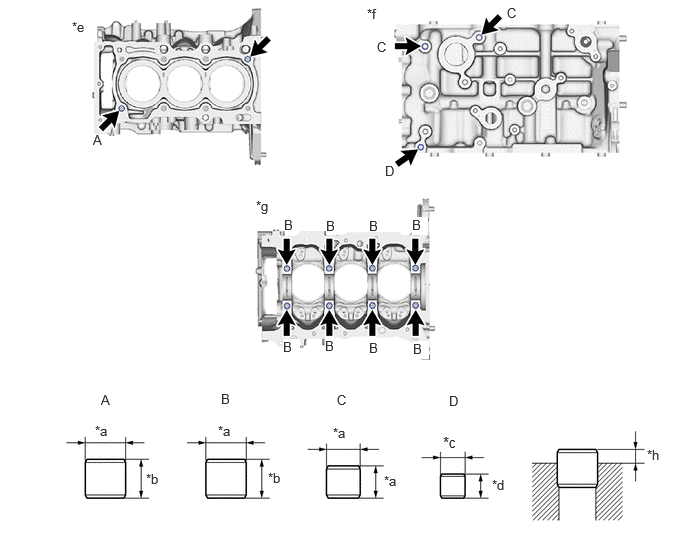
Remove the 10 ring pins.
b.
Using a plastic hammer, install 10 new ring pins.
0.75,0.198 1.063,0.396
0.313,0.198
10
false
*e
3.823,0.063 4.135,0.26
0.313,0.198
10
false
*f
2.667,2.063 2.979,2.26
0.313,0.198
10
false
*g
0.969,1.375 1.146,1.615
0.177,0.24
10
false
A
2.958,2.26 3.135,2.5
0.177,0.24
10
false
B
3.927,0.406 4.104,0.646
0.177,0.24
10
false
C
5.281,0.052 5.458,0.292
0.177,0.24
10
false
C
4.01,1.698 4.188,1.938
0.177,0.24
10
false
D
3.396,2.271 3.573,2.51
0.177,0.24
10
false
B
3.844,2.271 4.021,2.51
0.177,0.24
10
false
B
4.292,2.26 4.458,2.448
0.167,0.188
10
true
B
4.302,3.552 4.469,3.74
0.167,0.188
10
true
B
3.844,3.542 4.021,3.781
0.177,0.24
10
false
B
3.385,3.521 3.563,3.76
0.177,0.24
10
true
B
2.948,3.531 3.125,3.771
0.177,0.24
10
true
B
1.052,4.083 1.229,4.323
0.177,0.24
10
false
A
2.302,4.073 2.479,4.313
0.177,0.24
10
false
B
3.51,4.083 3.688,4.323
0.177,0.24
10
false
C
4.677,4.094 4.854,4.333
0.177,0.24
10
false
D
0.99,4.406 1.302,4.604
0.313,0.198
10
false
*a
1.521,4.906 1.833,5.104
0.313,0.198
10
false
*b
2.271,4.406 2.583,4.604
0.313,0.198
10
false
*a
2.792,4.896 3.104,5.094
0.313,0.198
10
false
*b
3.469,4.427 3.698,4.625
0.229,0.198
10
false
*a
4,4.927 4.229,5.125
0.229,0.198
10
false
*a
4.615,4.51 4.844,4.708
0.229,0.198
11
false
*c
5.125,4.969 5.354,5.167
0.229,0.198
10
false
*d
6.74,4.656 6.969,4.854
0.229,0.198
10
false
*h
| *a | 14 mm (0.551 in.) | *b | 12 mm (0.472 in.) |
| *c | 11 mm (0.433 in.) | *d | 8 mm (0.315 in.) |
| *e | Top Side | *f | LH Side |
| *g | Bottom Side | *h | Protrusion Height |
- Standard Protrusion Height:
- RING PIN (A, B, C):
5.0 to 7.0 mm (0.197 to 0.276 in.)
- RING PIN (D):
3.0 to 5.0 mm (0.118 to 0.197 in.)
2.REPLACE STRAIGHT PIN
- NOTICE:
-
It is not necessary to remove the straight pins unless they are being replaced.
a.
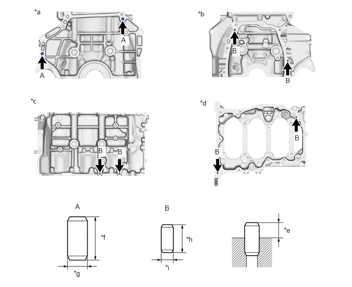
Remove the 8 straight pins.
b.
Using a plastic hammer, install 8 new straight pins.
2.469,0.729 2.625,0.927
0.156,0.198
10
true
A
0.813,1.448 0.969,1.646
0.156,0.198
10
true
A
4.729,0.948 4.885,1.146
0.156,0.198
10
true
B
5.813,1.552 5.969,1.75
0.156,0.198
10
true
B
4.375,3 4.531,3.198
0.156,0.198
10
true
B
6,2.719 6.156,2.917
0.156,0.198
10
true
B
2.396,3 2.552,3.198
0.156,0.198
10
true
B
2,2.979 2.156,3.177
0.156,0.198
10
true
B
3.365,5.354 3.677,5.552
0.313,0.198
10
false
*i
0.698,0.156 1.01,0.354
0.313,0.198
10
false
*a
4.031,0.198 4.344,0.396
0.313,0.198
10
false
*b
0.625,1.969 0.938,2.167
0.313,0.198
10
false
*c
4.073,2.01 4.385,2.208
0.313,0.198
10
false
*d
5.781,4.594 6.094,4.792
0.313,0.198
10
false
*e
3.792,4.781 4.104,4.979
0.313,0.198
10
false
*h
1.5,5.469 1.813,5.667
0.313,0.198
10
false
*g
2.052,4.74 2.365,4.938
0.313,0.198
10
false
*f
1.531,4.115 1.688,4.313
0.156,0.198
10
true
A
3.354,4.146 3.51,4.344
0.156,0.198
10
true
B
| *a | Rear Side | *b | Front Side |
| *c | RH Side | *d | Bottom Side |
| *e | Protrusion Height | *f | 22 mm (0.866 in.) |
| *g | 10 mm (0.394 in.) | *h | 14 mm (0.551 in.) |
| *i | 6.0 mm (0.236 in.) | - | - |
- Standard Protrusion Height:
Straight Pin Specified Condition (A) 11.0 to 13.0 mm (0.433 to 0.512 in.) (B) 5.0 to 7.0 mm (0.197 to 0.276 in.)