RM36W0E
_52
Drivetrain
_095692
GF1A TRANSFER / 4WD / AWD
_0449396
4WD CONTROL SWITCH
G
GF1A TRANSFER / 4WD / AWD 4WD CONTROL SWITCH INSPECTION
PROCEDURE

 84970E
1.INSPECT 4WD CONTROL SWITCH (NO. 2 COMBINATION SWITCH ASSEMBLY)
a.
Inspect the resistance:
i.
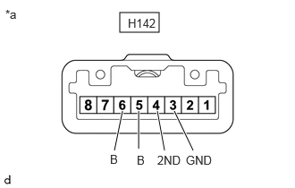
1.396,0.146 1.854,0.375
0.458,0.229
1.333,1.75 1.427,1.292
true
1.615,1.729 1.615,1.292
true
1.917,1.75 1.833,1.292
true
2.25,1.75 2.031,1.292
true
0.063,0.083 0.375,0.24
0.313,0.156
10
false
*a
1.49,0.188 1.885,0.385
0.396,0.198
10
false
H142
1.281,1.771 1.438,1.969
0.156,0.198
10
false
B
1.594,1.781 1.75,1.979
0.156,0.198
10
false
B
1.833,1.781 2.156,2
0.323,0.219
10
false
2ND
2.167,1.781 2.49,2
0.323,0.219
10
false
GND
| *a | Component without harness connected
4WD Control Switch (No. 2 Combination Switch Assembly) |
Measure the resistance according to the value(s) in the table below.
- Standard Resistance:
Tester Connection Switch Condition Specified Condition H142-5 (B) - H142-3 (GND) NORMAL mode switch being pushed and held Below 1 Ω NORMAL mode switch not pushed 10 kΩ or higher H142-6 (B) - H142-3 (GND) TRACK mode switch being pushed and held Below 1 Ω TRACK mode switch not pushed 10 kΩ or higher H142-4 (2ND) - H142-3 (GND) SPORT mode switch being pushed and held Below 1 Ω SPORT mode switch not pushed 10 kΩ or higher
ii.
If the result is not as specified, replace the 4WD control switch (No. 2 combination switch assembly).
b.
1.396,0.146 1.854,0.375
0.458,0.229
1.219,1.729 1.219,1.292
true
2.208,1.729 2.208,1.292
true
0.063,0.083 0.375,0.24
0.313,0.156
10
false
*a
1.49,0.188 1.885,0.385
0.396,0.198
10
false
H142
1.125,1.781 1.458,1.979
0.333,0.198
10
false
ILL+
2.135,1.781 2.51,2.021
0.375,0.24
10
false
ILL-
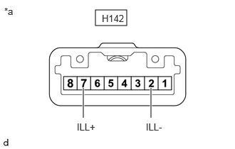
| *a | Component without harness connected
4WD Control Switch (No. 2 Combination Switch Assembly) |
Inspect the illumination:
i.
Apply battery voltage to the integration control and panel assembly (multi-terrain select switch) and check that the switch illuminates.
- OK:
Condition Specified Condition Auxiliary battery positive (+) → H142-7 (ILL+)
Auxiliary battery positive (-) → H142-2 (ILL-)Illuminates
ii.
If the result is not as specified, replace the 4WD control switch (No. 2 combination switch assembly).