AUDIO / VIDEO ACTIVE NOISE CONTROL SYSTEM B1AA696 Front Right Microphone Circuit Component Internal Failure B1AA71C Front Right Microphone Circuit Circuit Voltage Out of Range
DESCRIPTION
These DTCs are stored when a malfunction occurs in the active noise control microphone RH system.
| DTC No. | Detection Item | DTC Detection Condition | Trouble Area |
|---|---|---|---|
| B1AA696 | Front Right Microphone Circuit Component Internal Failure | Stereo component equalizer assembly detects malfunction in active noise control microphone RH for 4 seconds or more continuously when engine speed is 1200 rpm or more* | ·
Harness or connector ·
Active noise control microphone RH ·
Stereo component equalizer assembly |
| B1AA71C | Front Right Microphone Circuit Circuit Voltage Out of Range | Stereo component equalizer assembly detects active noise control microphone RH connection malfunction for 4 seconds or more continuously* | ·
Harness or connector ·
Active noise control microphone RH ·
Stereo component equalizer assembly |
- HINT:
-
*: Malfunction monitoring is not performed under the following conditions, in order to prevent erroneous detection.
- ·
After ignition switch is turned to ACC for 3 seconds or more.
·After the auxiliary battery voltage returns to normal for 3 seconds.
·Before 3 seconds have elapsed after auxiliary battery voltage has returned to normal.
WIRING DIAGRAM
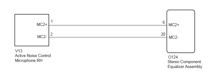
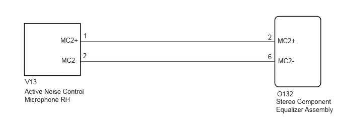
PROCEDURE
Clear the DTCs.
- Body Electrical > Active Noise Control > Clear DTCs
- 50002 415
- Result:
Proceed to NEXT
NEXT
Check for DTCs.
- Body Electrical > Active Noise Control > Trouble Codes
- 50001 415
- Result:
Result Proceed to DTC B1AA696 and B1AA71C are not output A DTC B1AA696 and B1AA71C are output B
A
Click hereGeneral>INTRODUCTION>HOW TO TROUBLESHOOT ECU CONTROLLED SYSTEMS>HOW TO PROCEED WITH TROUBLESHOOTING
B
Choose the model to be inspected.
- Result:
Result Proceed to w/ Stereo Component Amplifier Assembly A w/o Stereo Component Amplifier Assembly B
A
B
Disconnect the O124 stereo component equalizer assembly connector.
Disconnect the V13 active noise control microphone RH connector.
Measure the resistance according to the value(s) in the table below.
- Standard Resistance:
Tester Connection Condition Specified Condition O124-6 (MC2+) - V13-1 (MC2+) Always Below 1 Ω O124-20 (MC2-) - V13-2 (MC2-) Always Below 1 Ω O124-6 (MC2+) - Body ground Always 10 kΩ or higher O124-20 (MC2-) - Body ground Always 10 kΩ or higher
- Result:
Proceed to OK NG
OK
NG
Replace the active noise control microphone RH with a new or known good one.
Click hereAudio / Visual / Telematics>AUDIO / VIDEO>ACTIVE NOISE CONTROL MICROPHONE>REMOVAL
- Result:
Proceed to NEXT
NEXT
Clear the DTCs.
- Body Electrical > Active Noise Control > Clear DTCs
- 50002 415
- Result:
Proceed to NEXT
NEXT
Check for DTCs.
- Body Electrical > Active Noise Control > Trouble Codes
- 50001 415
- Result:
Result Proceed to DTC B1AA696 and B1AA71C are not output A DTC B1AA696 and B1AA71C are output B
A
B
Disconnect the O132 stereo component equalizer assembly connector.
Disconnect the V13 active noise control microphone RH connector.
Measure the resistance according to the value(s) in the table below.
- Standard Resistance:
Tester Connection Condition Specified Condition O132-2 (MC2+) - V13-1 (MC2+) Always Below 1 Ω O132-6 (MC2-) - V13-2 (MC2-) Always Below 1 Ω O132-2 (MC2+) - Body ground Always 10 kΩ or higher O132-6 (MC2-) - Body ground Always 10 kΩ or higher
- Result:
Proceed to OK NG
OK
NG
Replace the active noise control microphone RH with a new or known good one.
Click hereAudio / Visual / Telematics>AUDIO / VIDEO>ACTIVE NOISE CONTROL MICROPHONE>REMOVAL
- Result:
Proceed to NEXT
NEXT
Clear the DTCs.
- Body Electrical > Active Noise Control > Clear DTCs
- 50002 415
- Result:
Proceed to NEXT
NEXT
Check for DTCs.
- Body Electrical > Active Noise Control > Trouble Codes
- 50001 415
- Result:
Result Proceed to DTC B1AA696 and B1AA71C are not output A DTC B1AA696 and B1AA71C are output B
A
B