GF1A TRANSFER / 4WD / AWD ACTIVE TORQUE SPLIT AWD SYSTEM TERMINALS OF ECU
CHECK 4WD ECU ASSEMBLY

Measure the voltage and resistance of the connector.
| Terminal No. (Symbol) | Terminal Description | Condition | Specified Condition |
|---|---|---|---|
| O119-1 (GND) - Body ground | Ground | Always | Below 1 Ω |
| O119-2 (BSLC) - O119-1 (GND) | 4WD ECU assembly power supply | Always | 11 to 14 V |
| O119-13 (T1H) - O119-1 (GND) | Temperature sensor (+) input | Ignition switch ON | 0.5 to 4.5 V |
| O119-21 (T1L) - O119-1 (GND) | Temperature sensor (-) input | Ignition switch ON | 0.5 to 4.5 V |
| O119-24 (IG1) - O119-1 (GND) | 4WD ECU assembly power supply input | Ignition switch ON | 11 to 14 V |
| O120-3 (SLC-) - O119-1 (GND) | 4WD linear solenoid (transmission coupling assembly) (-) output | Ignition switch ON | Below 0.5 V |
| O120-4 (SLC+) - O119-1 (GND) | 4WD linear solenoid (transmission coupling assembly) (+) output | Ignition switch ON | Below 0.5 V |
| O120-17 (CANH) - O120-26 (CANL) | CAN communication line | Ignition switch off | 54 to 69 Ω |
CHECK ECM
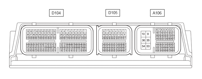
- HINT:
-
The standard voltage, resistance and waveform between each pair of the ECM terminals is shown in the table below.
-
The appropriate conditions for checking each pair of the terminals are also indicated. The result of checks should be compared with the standard voltage, resistance and waveform for each pair of the terminals as displayed in the Specified Condition column. The illustration above can be used as a reference to identify the ECM terminal locations.
Measure the voltage and resistance of the connector.
| Terminal No. (Symbol) | Terminal Description | Condition | Specified Condition |
|---|---|---|---|
| A106-10(E1) - Body ground | Ground | Always | Below 1 Ω |
| A106-31 (PWMS) - A106-10 (E1) | SPORT mode switch input | ·
Ignition switch ON ·
4WD control switch (No. 2 combination switch assembly) held in operation position |
4.5 to 5.5 V |
·
Ignition switch ON ·
4WD control switch (No. 2 combination switch assembly) not held in operation position |
11 to 14 V | ||
| A106-24 (TRMS) - A106-10 (E1) | TRACK mode switch input | ·
Ignition switch ON ·
4WD control switch (No. 2 combination switch assembly) held in operation position |
4.5 to 5.5 V |
·
Ignition switch ON ·
4WD control switch (No. 2 combination switch assembly) not held in operation position |
11 to 14 V | ||
| A106-51 (SPCN) - A106-10 (E1) | NORMAL mode switch input | ·
Ignition switch ON ·
4WD control switch (No. 2 combination switch assembly) held in operation position |
4.5 to 5.5 V |
·
Ignition switch ON ·
4WD control switch (No. 2 combination switch assembly) not held in operation position |
11 to 14 V |