AUDIO / VIDEO AUDIO AND VISUAL SYSTEM(for Radio and Display Type with TAS Type) DTC CHECK / CLEAR
START DIAGNOSTIC MODE
- HINT:
- ·
Illustrations may differ from the actual vehicle screen depending on the device settings and options. Therefore, some detailed areas may not be shown exactly the same as on the actual vehicle screen.
·Make sure that the system does not have an active connection to an Android Auto or Apple CarPlay device in order to prevent voice recognition from being activated.
·If the system cannot enter diagnostic mode, inspect all AVC-LAN communication components and repair or replace the malfunctioning parts.
Turn the ignition switch to ON.
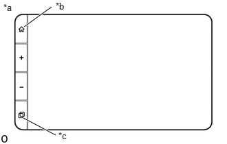
| *a | Example |
| *b | HOME Switch |
| *c | Function Switch |
While pressing and holding the function switch, press the HOME switch 3 times.
SYSTEM OVERVIEW
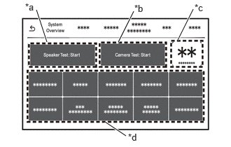
System overview screen description
| Display | Content |
|---|---|
| *a: Speaker Test | Pressing "Speaker Test: Start" will begin playing beep sounds from each speaker, and the test pattern will repeat until "Speaker Test: Stop" is pressed. |
| *b: Camera Test | If a rear television camera is detected, pressing "Camera Test: Start" will display the video feed from the rear television camera even if the shift lever is not in R. |
| *c: Identification Mark | Toyota part number and related identification mark are shown in this area. |
| *d: Status Indicators | Displays the status of each system.
·
Green: Functioning normally, no abnormality ·
Gray: Item not functional or function cannot be confirmed, no abnormality ·
Red: Malfunction |
| Item | Green Status | Gray Status | Red Status |
|---|---|---|---|
|
*1: Only shown if applicable *2: Only shown if no stereo component amplifier assembly |
|||
| Rear view camera | Rear television camera assembly detected | Rear television camera assembly not detected | ·
Previously detected, but disconnected ·
Short to ground ·
Short to VCC |
| External amplifier* | AVC-LAN communication functional | - | AVC-LAN communication not functional (no periodical messages) |
| Speakers* | No faults detected during ACC | Fault detection information not available (e.g. fault list cleared during current ACC cycle) | ·
Short circuit detected (GND, VCC) ·
Detection at runtime ·
Open circuit, speaker wires short to each other (detection once only on startup) |
| Microphone | Connected (SNS signal to GND) | - | SNS signal OPEN |
| GPS antenna | GPS signal from at least 1 satellite received | No faults, but no GPS signal received | ·
Short to GND/VCC ·
Open |
| DAB antenna | No fault detected | - | ·
Short to GND/VCC ·
Open |
| FM antenna | Reception above threshold | No faults, but reception below threshold | Short to GND |
| CAN communication | ·
No bus error condition ·
Predefined set of periodical messages received ·
Error threshold for message not received is 5 periods per message |
IG OFF | ·
No communication detected (list of predefined messages) ·
Error state detected on bus |
| MM-SUB-BUS communication | ·
No bus off condition, predefined set of periodical messages received ·
Error threshold for message not received is 5 periods per message |
- | ·
Bus off condition detected ·
No communication detected |
| DCM600 | Telephone transceiver connected to the network (Telephone transceiver indicates primary APN connected) | Telephone transceiver connected by USB but no network traffic (Telephone transceiver indicates primary APN not connected) | ·
Telephone transceiver is physically not connected / abnormal connection (short/open) ·
Pairing unsuccessful (handshake) |
| USB | USB device connected | No faults, but no device connected | Short detected |
FAULTS
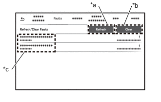
Faults screen description
| Item | Content |
|---|---|
| *a: Refresh | Refresh the fault list. |
| *b: Clear | Removes all the faults from the list. |
| *c: Fault list | ·
List of faults occurring in the system. See below table for list of possible faults. ·
A fault can be active (currently being detected) or passive (was detected in the past, but not active anymore). ·
The number of occurrences is also shown. |
| Fault Name | Description | Troubleshooting |
|---|---|---|
| Display has overheated | High temperature detected in display area. System will turn off. Once it is back to normal temperature system will be turned on automatically. | Replace radio and display receiver assembly if it was not operated in a high temperature environment where an overheating would be likely to occur. |
| Head Unit has overheated | High temperature detected in chassis area. System will turn off. Once it is back to normal temperature head unit will be turned on automatically. | Replace radio and display receiver assembly if it was not operated in a high temperature environment where an overheating would be likely to occur. |
| Amplifier has overheated | High temperature detected in internal amplifier area. System will turn off. Once it is back to normal temperature head unit will be turned on automatically. | Replace radio and display receiver assembly if it was not operated in a high temperature environment where an overheating would be likely to occur. |
| Battery Voltage High | Auxiliary battery voltage above 16.5 V is detected. If normal voltage is not detected within 3 seconds then head unit will be turned off. | Check power supply (auxiliary battery voltage). If supplied voltage is confirmed to be in range, replace radio and display receiver assembly. |
| Battery Voltage Low | Auxiliary battery voltage below 8 V is detected. If normal voltage is not detected within 3 seconds then head unit will be turned off. | Check power supply (auxiliary battery voltage). If supplied voltage is confirmed to be in range, replace radio and display receiver assembly. |
| Front/rear/left/right speaker's ground is shorted | Speaker wire is shorted to vehicle GND (applies to internal amplifier). | Check speaker wiring. |
| Front/rear/left/right speaker's VCC is shorted | Speaker wire is shorted to vehicle battery (applies to internal amplifier). | Check speaker wiring. |
| Front/rear/left/right speaker is not connected | Speaker wire is not connected (applies to internal amplifier). | Check speaker wiring. |
| Front/rear/left/right speaker's wires is shorted | Speaker wires are shorted to each other (applies to internal amplifier). | Check speaker wiring. |
| There is a malfunction in the Gyro | Internal error detected in gyroscope component. | Replace radio and display receiver assembly. |
| SWC button is stuck | System is detecting continuous input from steering pad switch assembly. | ·
Check that all steering pad switch assembly buttons are functioning and none of them are physically stuck. ·
Check steering pad switch assembly wire connection. |
| Face plate button is stuck | System is detecting continuous input from radio and display assembly panel switch button. | Check that all radio and display assembly panel switch buttons are functioning and none of them are physically stuck. |
| There is a malfunction in BT | Internal error detected in Bluetooth component. | Replace radio and display receiver assembly. |
| External Mic is disconnected | System is detecting that external microphone is not connected based on SNS signal input. | Check telephone microphone assembly wiring. |
| There is a malfunction in the USB | Electrical fault detected on USB connector. | Check for shorts of USB power line, USB device and USB connector. |
| Camera's VCC is shorted | Rear television camera assembly power supply (V+) is shorted to vehicle battery. | Check rear television camera assembly and wiring. |
| Camera's ground is shorted | Rear television camera assembly power supply (V+) is shorted to vehicle ground. | Check rear television camera assembly and wiring. |
| Signal lost from Camera | Rear television camera assembly signal is lost. | Check rear television camera assembly and wiring. |
| Tuner's ground is shorted | FM antenna signal is shorted to vehicle ground. | Check FM antenna and wiring. |
| EEP ROM not initialisation failed | EEP memory content is corrupted or has not been programmed correctly. | Replace radio and display receiver assembly. |
| Diranna initialisation failed | System has detected internal error in radio tuner component. | Replace radio and display receiver assembly. |
| Watchdog reset | There is a communication malfunction between 2 components in the system (IOC and SOC). | Replace radio and display receiver assembly. |
| GPS hardware has failed | System is detecting error with GPS/GNSS component. | Replace radio and display receiver assembly. |
| GPS ground is shorted | GPS/GNSS antenna shorted to vehicle ground. | Check GPS antenna connection. |
| GPS circuit is open | GPS/GNSS antenna circuit open (disconnected). | Check GPS antenna connection. |
| GPS VCC is shorted | GPS/GNSS antenna shorted to vehicle battery. | Check GPS antenna connection. |
| DAB circuit is open | DAB antenna circuit open (disconnected). | Check DAB antenna connection. |
| DAB ground is shorted | DAB antenna shorted to vehicle ground. | Check DAB antenna connection. |
| DAB VCC is shorted | DAB antenna shorted to vehicle battery. | Check DAB antenna connection. |
| External Amplifier open | Problem detected with AVC-LAN communication with stereo component amplifier assembly. | Check stereo component amplifier assembly data connection or stereo component amplifier assembly wiring. |
| DCM ground is shorted | An issue with power supply of telephone transceiver is detected. | Check telephone transceiver connector and wiring for electrical faults. |
| DCM network interface error | Network sharing interface with telephone transceiver could not be established. | ·
Ensure telephone transceiver is connected. ·
Confirm telephone transceiver function or replace telephone transceiver. |
| DCM connection error | USB connection to telephone transceiver cannot be confirmed. | Confirm wiring between radio and display receiver assembly and telephone transceiver. |
| DCM service protocol error | Ttelephone transceiver communication protocol is returning and error. | ·
Perform battery cycle ·
Confirm telephone transceiver function or replace telephone transceiver |
| Meter Global CAN faulty | Messages from combination meter assembly not received by radio and display receiver assembly. | Check CAN interface connection of radio and display receiver assembly and combination meter assembly |
| BDB Global CAN faulty | Messages from main body ECU (multiplex network body ECU) not received by radio and display receiver assembly. | Check CAN interface connection of radio and display receiver assembly and main body ECU (multiplex network body ECU) |
| ENG Global CAN faulty | Messages from ECM not received by radio and display receiver assembly. | Check CAN interface connection of radio and display receiver assembly and ECM |
| Meter Local CAN faulty | Messages from combination meter assembly not received on MM-SUB-Bus. | Check local CAN connection to radio and display receiver assembly and combination meter assembly. |
| CAN bus is off | CAN bus off condition detected on MM-SUB-Bus. | Check local CAN connection to radio and display receiver assembly and combination meter assembly. |
LOGGING
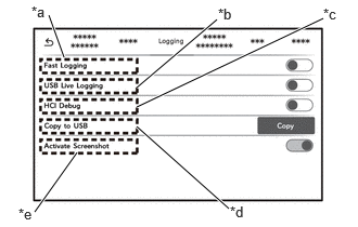
Logging screen description
| Item | Content |
|---|---|
| *a: Fast Logging | These features are for development purposes only. These items are disabled for production systems. |
| *b: USB Live Logging | |
| *c: HCI Debug | |
| *d Copy to USB | |
| *e: Activate Screenshot | If a USB drive (FAT32 formatted) is inserted into USB port, this function can be enabled. When enabled, press function switch to store a screenshot of the device onto the USB drive. |
SYSTEM PARAMETERS
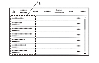
System Parameters screen description
| Item | Content |
|---|---|
| *a: System Parameters | Displays the output of various parameters. |
| Item | Content |
|---|---|
| ACC signal | ACC signal input state |
| IG signal | IG signal input state (CAN-bus and/or analog input) |
| Parking brake signal | PKB signal input state (CAN-bus and/or analog input) |
| Reverse gear signal | REV signal input state (CAN-bus and/or analog input) |
| ILL signal | ILL signal input state (analog input) |
| ADIM signal | ADIM signal input state (CAN-bus input) |
| Vehicle speed | Vehicle speed signal input state (CAN-bus or analog input) |
| System time | Current GPS time (UTC timezone) |
| Tuner frequency | Currently selected frequency for FM/DAB |
| Tuner station name | Currently selected station name for FM/DAB |
| Tuner signal strength | Signal strength for currently playing FM/DAB station |
| Bluetooth signal strength | Signal strength for currently connected Bluetooth device |
| GPS number of satellites | Number of satellites currently received by GNSS receiver |
| GPS fix status | Current status for GNSS location (no fix, 2D fix, 3D fix) |
| GPS latitude | Current latitude coordinate calculated by GNSS receiver |
| GPS longitude | Current longitude coordinate calculated by GNSS receiver |
| Accelerometer | Output values from internal accelerometer |
| Gyroscope | Output values from internal gyroscope |
| CNR average | Average signal-to-noise ratio for GNSS receiver |
| Battery voltage | Current voltage level measured from auxiliary battery |
| Temperature CPU | Current temperature measured at CPU |
| Temperature amplifier | Current temperature measured at internal amplifier |
| Temperature display | Current temperature measured at display |
DCM
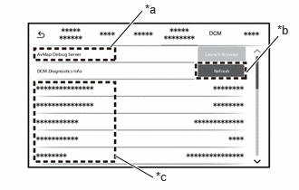
DCM screen description
| Item | Content |
|---|---|
| *a: AvMap Debug Server | This feature is for development purposes only. This item is disabled for production systems. |
| *b: Refresh | Press this button to update the parameter list. |
| *c: Parameter List | Parameter list received from telephone transceiver is displayed. The received parameters can vary. |
OTHER
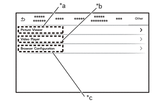
Other screen description
| Item | Content |
|---|---|
| *a: Picture Viewer | When a USB drive with pictures is inserted, these pictures can be displayed from this menu. Supported picture formats: GIF/JPG |
| *b: Video Player | When a USB drive with video files is inserted, these videos can be displayed from this menu. Supported video formats: MP4, M4V, 3GP, 3G2, Flash F4V(F4P, F4V, F4A, F4B), Nero Digital, QuickTime (MOV, QT), AVI |
| *c: Browser configuration | This feature is for development purposes only. This item is disabled for production systems. |
- HINT:
-
The user shall be able to block the touchscreen, hardkeys and steering pad switch assembly using the following key combination:
- 1.
Tap 3 times in bottom left corner of the touchscreen
2.Tap 3 times in top right corner of the touchscreen
-
The same combination shall unlock the touchscreen, hardkeys and steering pad switch assembly. A pop-up shall be shown (and autohide after 3s) to indicate user how to unlock the system
FINISH DIAGNOSTIC MODE
Turn the ignition switch off or press the HOME switch.