REMOVAL
Removal / installation · Vehicles built from Nov 2005
- NOTICE:
- Always use "Torx" socket wrench E10 when removing the rear seat.
| 1. DISCONNECT CABLE FROM NEGATIVE BATTERY TERMINAL |
| 2. REMOVE PACKAGE TRAY TRIM PANEL ASSEMBLY (w/ Package Tray Trim) |

Remove the 2 package tray trim suspenders.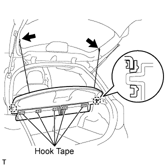

Remove the 5 pieces of hook tape.
Disengage the 2 claws and remove the package tray trim.
| 3. REMOVE DECK BOARD SUB-ASSEMBLY (w/ Deck Board) |
Release the 2 knobs and remove the deck board.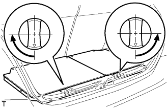
| 4. REMOVE SPARE WHEEL COVER ASSEMBLY (w/ Deck Board) |
Remove the spare wheel cover.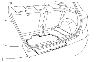
| 5. REMOVE DECK FLOOR BOX LH (w/ Deck Board) |
Release the 2 knobs and remove the deck floor box.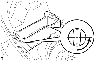
| 6. REMOVE REAR FLOOR CARPET ASSEMBLY (w/o Deck Board) |
Remove the rear floor carpet.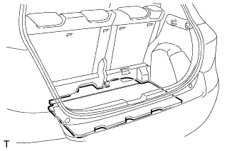
| 7. REMOVE NO. 2 REAR SEAT LEG COVER |
Disengage the 6 claws and remove the No. 2 rear seat leg cover.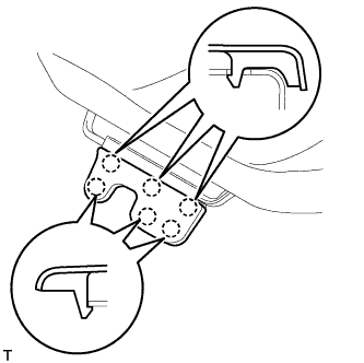
| 8. REMOVE REAR SEAT ASSEMBLY |
Using "Torx" socket wrench E10, remove the 3 bolts and pull up the rear seat cushion.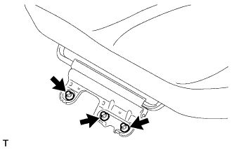
Using "Torx" socket wrench E10, remove the 4 bolts and the rear seat.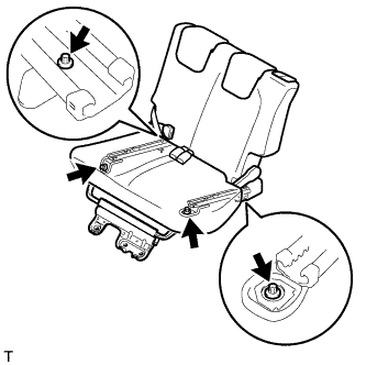
| 9. REMOVE REAR FLOOR SERVICE HOLE COVER |
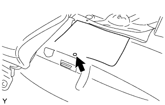 |
Remove the clip from the floor carpet.
Remove the rear floor service hole cover.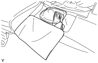
Disconnect the sender gauge connector.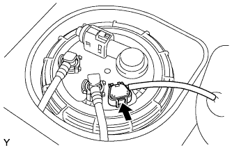
| 10. DISCONNECT FUEL TANK MAIN TUBE SUB-ASSEMBLY |
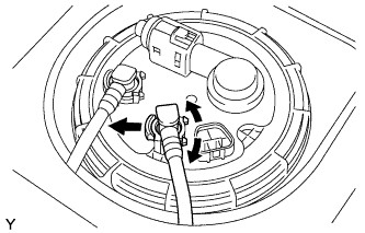 |
Widen the tip of the tube joint clip and pull it out.
Pull out the fuel tank main tube to disconnect it.
- NOTICE:
- Remove any dirt and foreign matter from the fuel tube connector before performing this work.
- Do not allow any scratches or foreign matter on the parts when disconnecting, as the fuel tube joint has the O-ring that seals the plug.
- Perform this work by hand. Do not use any tools.
- Do not forcibly bend, twist or turn the nylon tube.
- Protect the disconnected part by covering it with a plastic bag.
- If the nylon tube and fuel suction plate are stuck, push and pull to release them.
- Remove any dirt and foreign matter from the fuel tube connector before performing this work.
| 11. DISCONNECT FUEL RETURN TUBE SUB-ASSEMBLY |
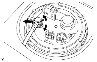 |
Widen the tip of the tube joint clip and pull it out.
Pull out the fuel tank main tube to disconnect it.
- NOTICE:
- Remove any dirt and foreign matter from the fuel tube connector before performing this work.
- Do not allow any scratches or foreign matter on the parts when disconnecting, as the fuel tube joint has the O-ring that seals the plug.
- Perform this work by hand. Do not use any tools.
- Do not forcibly bend, twist or turn the nylon tube.
- Protect the disconnected part by covering it with a plastic bag.
- If the nylon tube and fuel suction plate are stuck, push and pull to release them.
- Remove any dirt and foreign matter from the fuel tube connector before performing this work.
| 12. REMOVE FUEL PUMP GAUGE RETAINER |
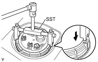 |
Using SST, remove the fuel pump gauge retainer.
- SST
- 09808-14020
(09808-01410, 09808-01420, 09808-01430)
- HINT:
- Align the claws of the fuel pump gauge retainer and the tips of SST.
| 13. REMOVE FUEL TANK VENT TUBE WITH SENDER GAUGE ASSEMBLY |
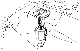 |
Remove the fuel tank vent tube with sender gauge from the fuel tank.
- NOTICE:
- Do not bend the arm of the sender gauge.
| 14. REMOVE FUEL TANK SUCTION TUBE GASKET |
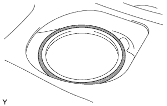 |
Remove the fuel suction tube gasket from the fuel tank.
| 15. REMOVE FUEL SENDER GAUGE ASSEMBLY |
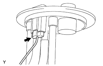 |
Disconnect the fuel sender gauge connector.
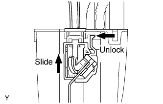
Unlock the fuel sender gauge, and slide and remove it.