REMOVAL
Removal / installation · Vehicles built from Jan 2006
- CAUTION:
- Some of these service operations affect the SRS airbag system. Read the precautionary notices concerning the SRS airbag system before servicing (Click here).
| 1. DISCONNECT CABLE FROM NEGATIVE BATTERY TERMINAL |

| 2. REMOVE FRONT WIPER ARM HEAD CAP |
Using a screwdriver with its tip wrapped in protective tape, disengage the claw and remove the 2 front wiper arm head caps.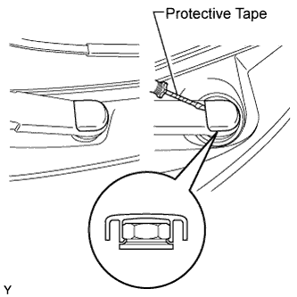

| 3. REMOVE FRONT WIPER ARM AND BLADE ASSEMBLY LH |
Operate the wiper, then stop the windshield wiper motor in the automatic stop position.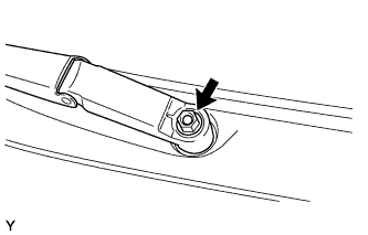
Remove the nut and front wiper arm.
| 4. REMOVE FRONT WIPER ARM AND BLADE ASSEMBLY RH |
- HINT:
- Use the same procedure as for the LH side.
| 5. REMOVE COWL SIDE VENTILATOR SUB-ASSEMBLY LH |
Using a screwdriver with its tip wrapped in protective tape, disengage the 3 claws and remove the cowl side ventilator sub-assembly LH.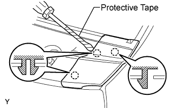
| 6. REMOVE COWL SIDE VENTILATOR SUB-ASSEMBLY RH |
- HINT:
- Use the same procedure as for the LH side.
| 7. REMOVE COWL TOP VENTILATOR LOUVER SUB-ASSEMBLY (for RHD) |
Disengage the 2 clips, the 6 claws and the 10 hooks.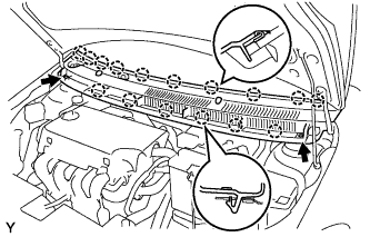
Remove the cowl top ventilator louver sub-assembly.
Disconnect the washer hoses.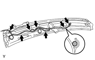
Disengage the 5 hooks.
| 8. REMOVE COWL TOP VENTILATOR LOUVER SUB-ASSEMBLY (for LHD) |
Disengage the 3 clips, the 4 claws and the 8 hooks.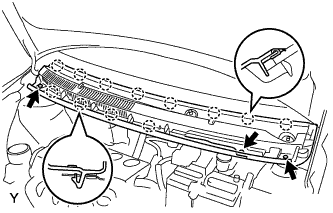
Remove the cowl top ventilator louver sub-assembly.
Disconnect the washer hoses.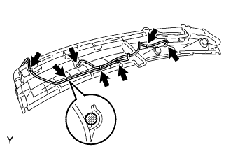
Disengage the 5 hooks.
| 9. REMOVE FRONT DOOR SCUFF PLATE RH |
Disengage the 11 claws and remove the front door scuff plate.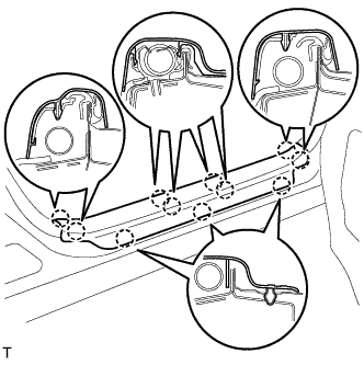
| 10. REMOVE FRONT DOOR SCUFF PLATE LH |
- HINT:
- Use the same procedure as for the RH side.
| 11. REMOVE COWL SIDE TRIM BOARD RH |
Disengage the claw and the stud bolt and remove the cowl side trim board.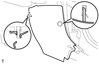
| 12. REMOVE COWL SIDE TRIM BOARD LH |
- HINT:
- Use the same procedure as for the RH side.
| 13. REMOVE FRONT DOOR OPENING TRIM WEATHERSTRIP RH |
Remove the front door opening trim weatherstrip.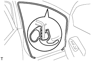
| 14. REMOVE FRONT DOOR OPENING TRIM WEATHERSTRIP LH |
- HINT:
- Use the same procedure as for the RH side.
| 15. REMOVE FRONT PILLAR GARNISH RH |
w/ Curtain Shield Airbag: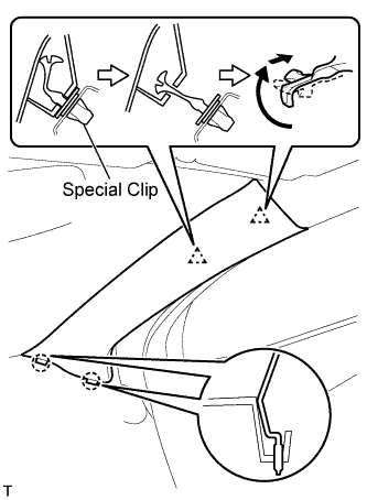
- NOTICE:
- Install a protective cover onto the curtain shield airbag as soon as the front pillar garnish is removed.
- Replace the special clip with a new one when the front pillar garnish is removed.
- Install a protective cover onto the curtain shield airbag as soon as the front pillar garnish is removed.
Disengage the 2 clips and the 2 claws and remove the front pillar garnish.
w/o Curtain Shield Airbag: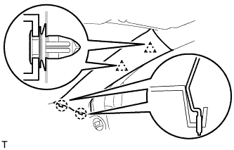
Disengage the 2 clips and the 2 claws and remove the front pillar garnish.
Disconnect the antenna connector.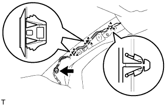
Using a clip remover, remove the 3 clamps.
w/ Curtain Shield Airbag: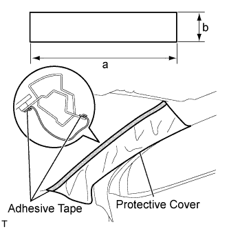
Completely cover the curtain shield airbag with a piece of cloth or nylon and fix the ends of the fabric with adhesive tape, as shown in the illustration.
- Protective cover size:
Area
Measurement
a
700 mm (27.56 in.)
b
120 mm (4.72 in.)
| 16. REMOVE FRONT PILLAR GARNISH LH |
w/ Curtain Shield Airbag: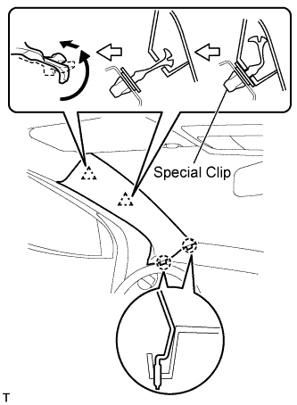
- NOTICE:
- Install a protective cover onto the curtain shield airbag as soon as the front pillar garnish is removed.
- Replace the special clip with a new one when the front pillar garnish is removed.
- Install a protective cover onto the curtain shield airbag as soon as the front pillar garnish is removed.
Disengage the 2 clips and the 2 claws and remove the front pillar garnish.
w/o Curtain Shield Airbag: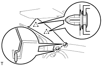
Disengage the 2 clips and the 2 claws and remove the front pillar garnish.
Using a clip remover, remove the 4 clamps.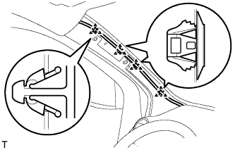
w/ Curtain Shield Airbag: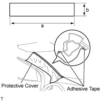
Completely cover the curtain shield airbag with a piece of cloth or nylon and fix the ends of the fabric with adhesive tape, as shown in the illustration.
- Protective cover size:
Area
Measurement
a
700 mm (27.56 in.)
b
120 mm (4.72 in.)
| 17. REMOVE ROOF HEADLINING SERVICE HOLE COVER (w/o Curtain Shield Airbag) |
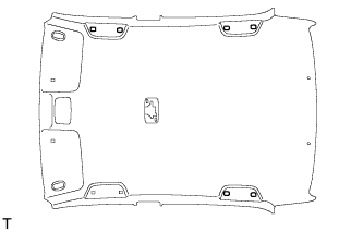 |
- HINT:
- The number of the roof headlining service hole covers varies with the specifications.
Using a clip remover with its tip wrapped in protective tape, remove the 2 roof headlining service hole covers.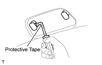
| 18. REMOVE ASSIST GRIP COVER |
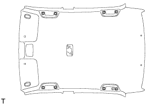 |
- HINT:
- The number of the assist grip covers varies with the specifications.
Using a screwdriver with its tip wrapped in protective tape, disengage the 2 claws and remove the assist grip cover.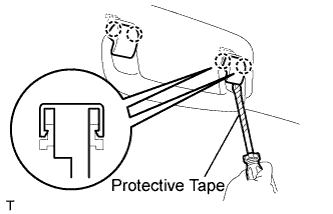
| 19. REMOVE ASSIST GRIP SUB-ASSEMBLY |
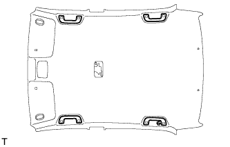 |
- HINT:
- The number of the assist grips varies with the specifications.
Disengage the 2 springs and remove the assist grip.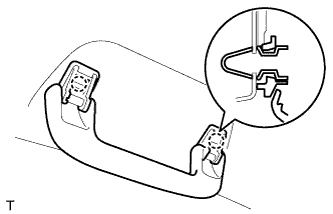
| 20. REMOVE VISOR ASSEMBLY RH |
Using a screwdriver with its tip wrapped in protective tape, disengage the 4 claws and remove the visor bracket cover.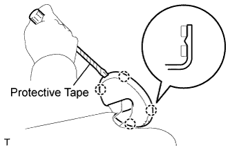
Remove the visor shaft from the visor holder.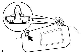
Disengage the 2 springs and remove the visor.
| 21. REMOVE VISOR ASSEMBLY LH |
- HINT:
- Use the same procedure as for the RH side.
| 22. REMOVE VISOR HOLDER RH |
Disengage the 2 claws by turning the visor counterclockwise between 60 to 120° and remove the visor holder.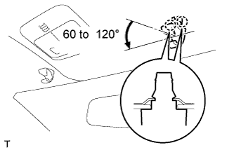
- HINT:
- The claw may be damaged during removal. However, it is reusable because this does not effect its function.
| 23. REMOVE VISOR HOLDER LH |
- HINT:
- Use the same procedure as for the RH side.
| 24. REMOVE ROOM LIGHT ASSEMBLY |
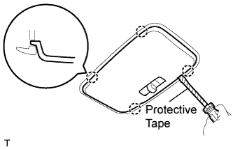 |
Using a screwdriver with its tip wrapped in protective tape, disengage the 4 claws and remove the room light lens.
Using a screwdriver with its tip wrapped in protective tape, disengage the 4 claws and remove the 2 covers.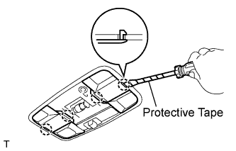
Using a screwdriver with its tip wrapped in protective tape, disengage the 4 claws.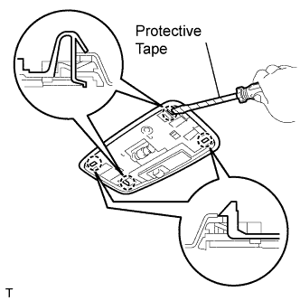
Disengage the roof wire from the claw of the room light.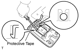
Using a screwdriver with its tip wrapped in protective tape, disengage the 4 claws and remove the room light switch base.
Remove room light bulb No. 1.
| 25. REMOVE MAP LIGHT ASSEMBLY |
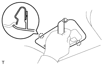 |
Using a roof moulding remover, disengage the 4 claws.
Disconnect the connector, and remove the map light.
| 26. REMOVE INNER REAR VIEW MIRROR |
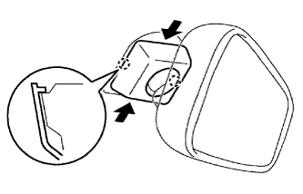 |
Pinch the cover, disengage the 2 claws and remove the cover.
Push the lever, and slide and remove the inner rear view mirror.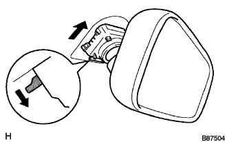
| 27. REMOVE ROOF HEADLINING ASSEMBLY |
- HINT:
- It is not necessary to remove the roof headlining completely. Slightly lower the front section of the roof headlining.
| 28. REMOVE WINDSHIELD OUTSIDE MOULDING |
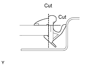 |
Using a knife, cut off the windshield outside moulding, as shown in the illustration.
- NOTICE:
- Do not damage the vehicle body with the knife.
Remove the windshield outside moulding.
- HINT:
- Make a partial cut in the windshield outside moulding. Then pull and remove it by hand.
| 29. REMOVE WINDSHIELD GLASS |
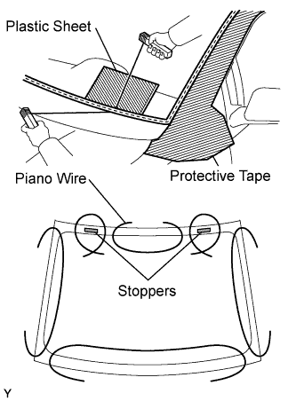 |
Apply protective tape to the outer circumference of the windshield glass, as shown in the illustration.
From the interior, insert piano wires between the vehicle body and the windshield glass, as shown in the illustration.
Tie objects that can serve as handles (for example, wooden blocks) to all wire ends.
- NOTICE:
- When separating the windshield glass from the vehicle, do not damage the vehicle's paintwork or exterior/interior ornaments.
- To prevent the safety pad from being scratched when removing the windshield glass, place a plastic sheet between the piano wire and safety pad.
- When separating the windshield glass from the vehicle, do not damage the vehicle's paintwork or exterior/interior ornaments.
Place matchmarks on the windshield glass and vehicle body in the locations indicated in the illustration.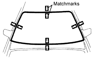
- HINT:
- Matchmarks do not need to be placed unless the windshield glass is going to be reused.
Cut through the adhesive by pulling the piano wire around the windshield glass.
Disengage the 2 stoppers.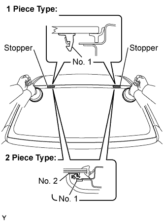
Using suction cups, remove the windshield glass.
- NOTICE:
- Leave as much adhesive on the vehicle body as possible when removing the windshield glass.