INSTALLATION
Removal / installation · Vehicles built from Aug 2005
- CAUTION:
- Some of these service operations affect the SRS airbag system. Read the precautionary notices concerning the SRS airbag system before servicing (Click here).
| 1. INSTALL INSTRUMENT PANEL WIRE ASSEMBLY |

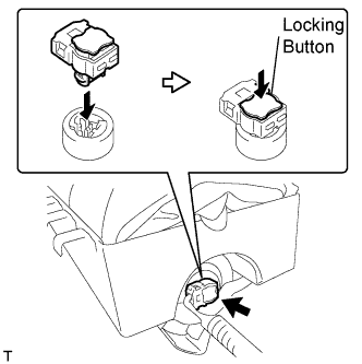  |
Connect the airbag connector to install the instrument panel wire.
- NOTICE:
- Lock the locking button securely.
| 2. INSTALL FRONT PASSENGER AIRBAG ASSEMBLY |
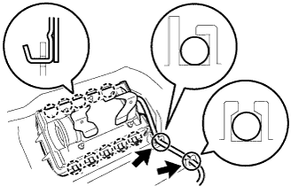 |
Engage the 10 hooks so that the connector side faces the outside of the vehicle, and install the instrument panel passenger airbag.
Install the wire harness onto the 2 claws of the instrument panel.
| 3. INSTALL UPPER INSTRUMENT PANEL SUB-ASSEMBLY |
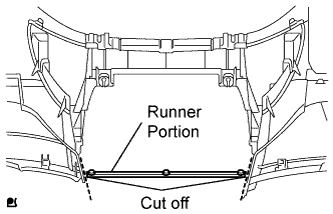 |
Using a nipper, cut off both ends of the runner portion shown in the illustration (When installing a new one).
Engage the 5 claws at the upper side of the instrument panel.
Engage the claw and the 3 clips at the lower side of the instrument panel.
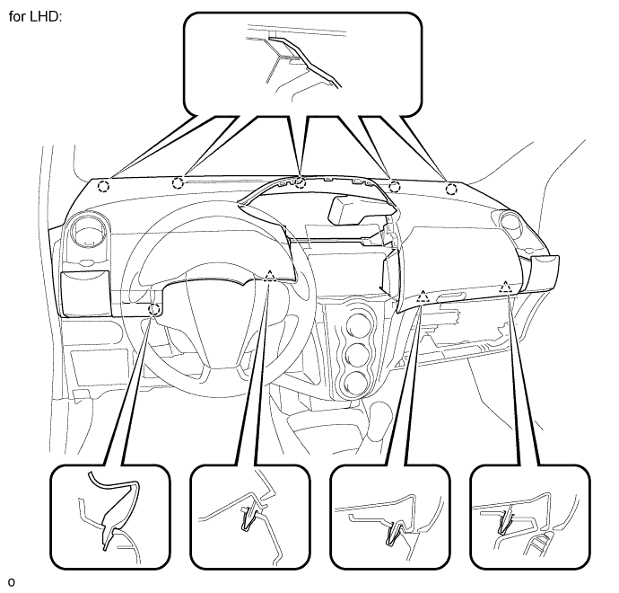
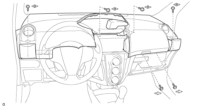
Install the instrument panel upper with the 2 <C> bolts and the 4 <B> screws.
- Torque:
- 20 N*m{ 204 kgf*cm , 15 ft.*lbf } for bolt
Connect the connectors.
Connect the passenger airbag connector and clamp.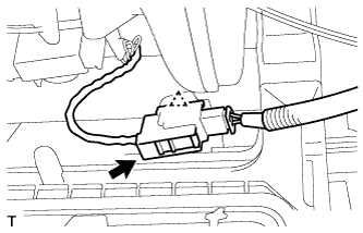
| 4. INSTALL SWITCH HOLE BASE |
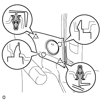 |
Disengage the 2 clips and 2 claws and install the switch hole base.
| 5. INSTALL GLOVE COMPARTMENT DOOR ASSEMBLY |
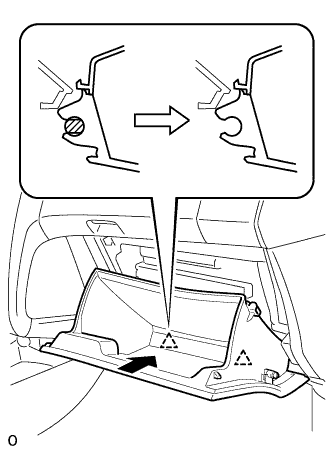 |
Engage the claw of the hinge portion in the horizontal direction to install the glove compartment door assembly.
- NOTICE:
- Engage the claw in the horizontal direction, otherwise, installation failure caused by excessive play around the hinge portion will result.
Slightly deform the upper portion of the glove compartment door assembly to engage the stopper.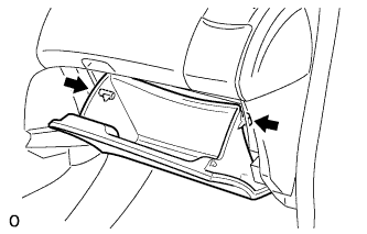
| 6. INSTALL COMBINATION METER ASSEMBLY |
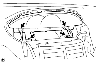 |
Install the combination meter assembly with the 2 screws.
Connect the 2 connectors.
| 7. INSTALL INSTRUMENT CLUSTER FINISH PANEL SUB-ASSEMBLY CENTER |
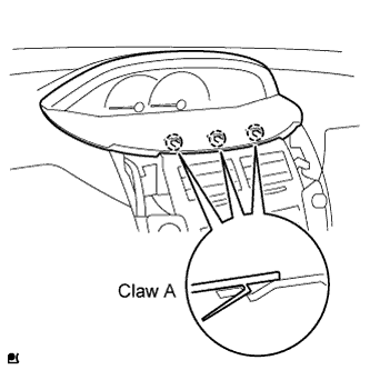 |
Fit the 3 A claws of the instrument cluster finish panel into the upper instrument cluster finish panel center.
Engage the 4 claws and 5 clips and install the instrument cluster finish panel.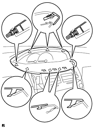
| 8. INSTALL INSTRUMENT CLUSTER FINISH PANEL |
|
|
Fit the 3 A claws of the instrument cluster finish panel into the upper instrument cluster finish panel center.
Engage the 4 claws and 5 clips and install the instrument cluster finish panel.
| 9. INSTALL INSTRUMENT PANEL FINISH PANEL END RH |
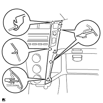 |
with CD player
Connect the connector.
Engage the 4 claws and 3 clips and install the instrument panel finish panel end RH.
Except CD player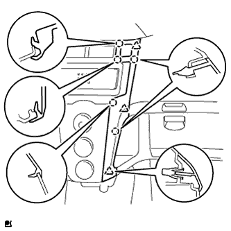
Connect the connector.
Engage the 5 claws and 3 clips and install the instrument panel finish panel end RH.
| 10. INSTALL INSTRUMENT PANEL FINISH PANEL END LH |
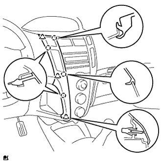 |
with CD player
Connect the connector.
Engage the 4 claws and 3 clips and install the instrument panel finish panel end LH.
Except CD player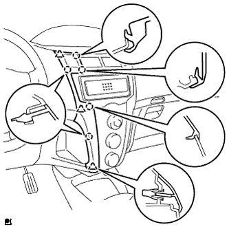
Connect the connector.
Engage the 5 claws and 3 clips and install the instrument panel finish panel end LH.
| 11. INSTALL FRONT PILLAR GARNISH RH |
w/ Curtain Shield Airbag: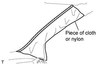
Remove the piece of cloth or nylon.
w/ Front No. 2 Speaker: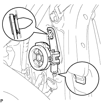
Insert the hook into the body hole.
Engage the clip and install the front speaker.
Connect the speaker connector.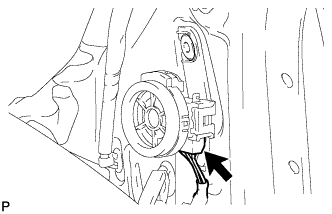
Install the 3 antenna cord clamps.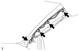
Connect the connector.
w/ Curtain Shield Airbag:
Install a new special clip and the clip onto a new front pillar garnish.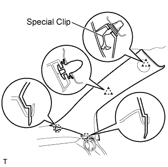
Engage the 2 clips and the 2 claws and install the front pillar garnish.
w/o Curtain Shield Airbag:
Engage the 2 clips and the 2 claws and install the front pillar garnish.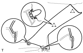
| 12. INSTALL FRONT PILLAR GARNISH LH |
w/ Curtain Shield Airbag: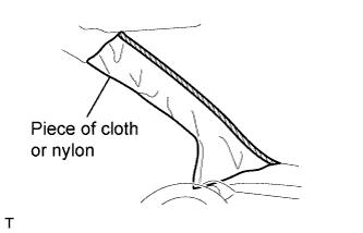
Remove the piece of cloth or nylon.
w/ Front No. 2 Speaker: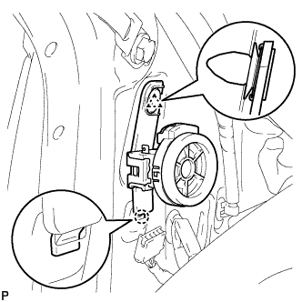
Insert the hook into the body hole.
Engage the clip and install the front speaker.
Connect the speaker connector.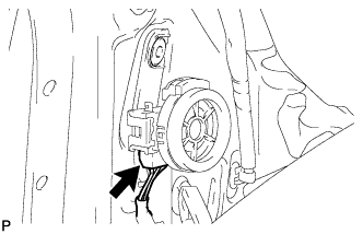
Install the 4 wire harness clamps.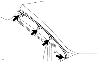
w/ Curtain Shield Airbag:
Install a new special clip and the clip onto a new front pillar garnish.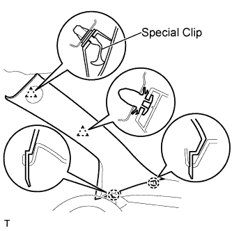
Engage the 2 clips and the 2 claws and install the front pillar garnish.
w/o Curtain Shield Airbag:
Engage the 2 clips and the 2 claws and install the front pillar garnish.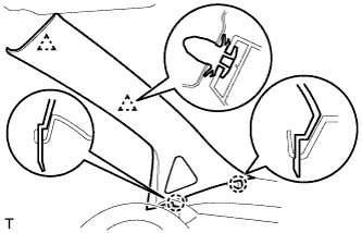
| 13. INSTALL FRONT DOOR OPENING TRIM WEATHERSTRIP RH |
Align the location mark with the paint mark first, and install the front door opening trim weatherstrip, as shown in the illustration.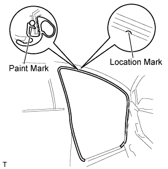
Paint mark: Area
Color
RH side
Gold
LH side
Silver
| 14. INSTALL FRONT DOOR OPENING TRIM WEATHERSTRIP LH |
- HINT:
- Use the same procedure for the RH side.
| 15. CONNECT CABLE TO NEGATIVE BATTERY TERMINAL |
- Torque:
- 5.4 N*m{ 55 kgf*cm , 48 in.*lbf }
| 16. INSPECT SRS WARNING LIGHT |