Versions by build date: Aug 2005 – Oct 2005from Nov 2005
INSPECT DAMPER SERVO MOTOR SUB-ASSEMBLY
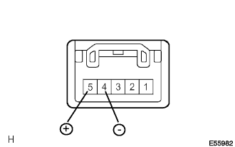
Connect the positive (+) battery lead to terminal 5 of each servo motor and the negative (-) battery lead to terminal 4. Check that the damper operates smoothly.
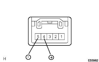
Connect the positive (+) battery lead to terminal 4 of each servo motor and the negative (-) battery lead to terminal 5. Check that the damper operates smoothly.
INSPECT NO. 1 COOLER THERMISTOR
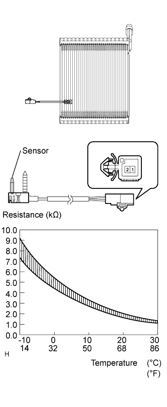
Measure the resistance.
Standard resistance:
Tester Connection
Condition
Specified Condition
1 - 2
-10°C (14°F)
7.30 to 9.10 kΩ
1 - 2
-5°C (23°F)
5.65 to 6.95 kΩ
1 - 2
0°C (32°F)
4.40 to 5.35 kΩ
1 - 2
5°C (41°F)
3.40 to 4.15 kΩ
1 - 2
10°C (50°F)
2.70 to 3.25 kΩ
1 - 2
15°C (59°F)
2.14 to 2.58 kΩ
1 - 2
20°C (68°F)
1.71 to 2.05 kΩ
1 - 2
25°C (77°F)
1.38 to 1.64 kΩ
1 - 2
30°C (86°F)
1.11 to 1.32 kΩ
NOTICE:
Touching the sensor even slightly may change the resistance value. Hold the connector of the sensor.
When measuring the resistance, the temperature of the sensor and the cooler thermistor must be the same.
HINT:
As the temperature increases, the resistance decreases (see the graph).
If the operation is not as specified, replace the cooler thermistor.
INSPECT PTC HEATER ASSEMBLY
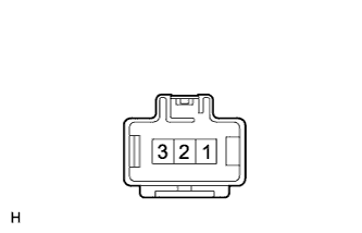
Measure the resistance.
Standard resistance:
Tester Connection
Specified Condition
1 - 2
Below 1 Ω
2 - 3
Below 1 Ω
1 - 3
Below 1 Ω
If the resistance value is not as specified, replace the PTC heater assembly.