REASSEMBLY
Removal / installation · Vehicles built from Aug 2005
| 1.
INSTALL OUTPUT SHAFT FRONT BEARING |
 |
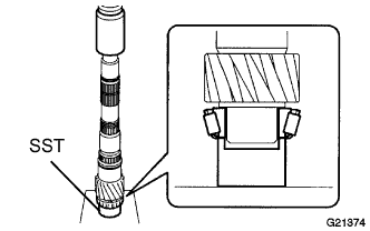
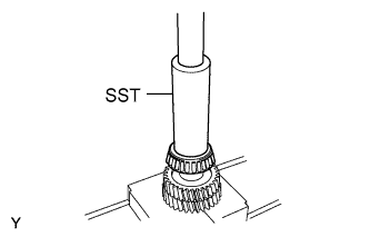
Using SST and a press, install the output shaft front bearing onto the output shaft.
- SST
- 09710-22021
(09710-01051)
| 2.
INSTALL 1ST GEAR NEEDLE ROLLER BEARING |
|
Coat the 1st gear needle roller bearing with gear oil, and install it onto the output shaft.
| 3.
INSTALL 1ST GEAR |
|
Coat the 1st gear with gear oil, and install it onto the output shaft.
| 4.
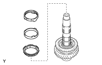
INSTALL 1ST GEAR SYNCHRONIZER RING |
|
Coat the 1st gear synchronizer ring with gear oil, and install it onto the 1st gear.
| 5.
INSTALL TRANSMISSION CLUTCH HUB NO.1 |
|
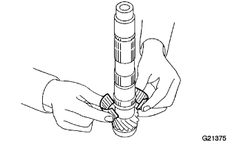
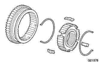
Install 2 shifting key springs No. 1, 3 shifting keys No. 1 and the reverse gear onto transmission clutch hub No. 1.
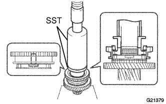
- Using SST and a press, install transmission clutch hub No. 1 onto the output shaft.
- SST
- 09316-60011
(09316-00011, 09316-00071)
- NOTICE:
- Install the reverse gear assembly in the correct orientation, as shown in the illustration.
| 6.
INSTALL CLUTCH HUB NO.1 SHAFT SNAP RING |
|
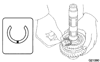
Select a snap ring that allows the minimum axial play.
- Standard clearance:
- 0 to 0.1 mm (0 to 0.0039 in.)
Mark
|
Thickness mm (in.)
|
Mark
|
Thickness mm (in.)
|
A
|
2.28 (0.0898)
|
D
|
2.46 (0.0969)
|
B
|
2.34 (0.0921)
|
E
|
2.52 (0.0992)
|
C
|
2.40 (0.0945)
|
F
|
2.58 (0.1016)
|
- Using a snap ring expander, install the new snap ring onto the output shaft.
| 7.
INSPECT 1ST GEAR THRUST CLEARANCE |
|
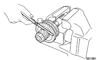
Using a feeler gauge, measure the 1st gear thrust clearance.
- Standard clearance:
- 0.10 to 0.45 mm (0.0039 to 0.0177 in.)
- Maximum clearance:
- 0.45 mm (0.0177 in.)
If the clearance exceeds the maximum, replace the 1st gear synchronizer ring.
| 8.
INSPECT 1ST GEAR RADIAL CLEARANCE |
|
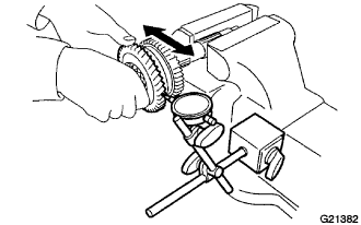
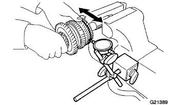
Using a dial indicator, measure the 1st gear radial clearance.
- Standard clearance:
- 0.015 to 0.056 mm (0.0006 to 0.0022 in.)
- Maximum clearance:
- 0.056 mm (0.0022 in.)
If the clearance exceeds the maximum, replace the 1st gear needle roller bearing or the shaft.
| 9.
INSTALL 2ND GEAR BEARING SPACER |
|
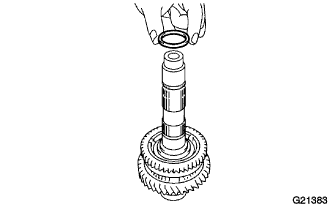
Coat the 2nd gear bearing spacer with gear oil, and install it onto the output shaft.
| 10.
INSTALL 2ND GEAR NEEDLE ROLLER BEARING |
|
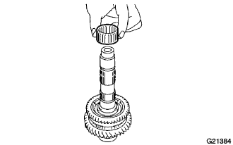
Coat the 2nd gear needle roller bearing with gear oil, and install it onto the output shaft.
| 11.
INSTALL 2ND GEAR SYNCHRONIZER RING |
|
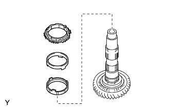
Coat the 2nd synchronizer ring with gear oil, and install it onto the reverse gear.
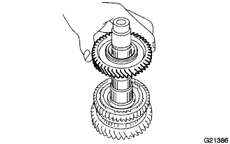
| 12.
INSTALL 2ND GEAR |
|
Coat the 2nd gear with gear oil, and install it onto the output shaft.
| 13.
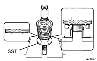
INSTALL 3RD DRIVEN GEAR |
|
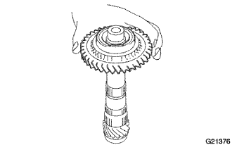
Using SST and a press, install the 3rd driven gear onto the output shaft.
- SST
- 09316-60011
(09316-00041)
| 14.
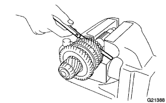
INSPECT 2ND GEAR THRUST CLEARANCE |
|
Using a feeler gauge, measure the 2nd gear thrust clearance.
- Standard clearance:
- 0.10 to 0.55 mm (0.0039 to 0.0217 in.)
- Maximum clearance:
- 0.55 mm (0.0217 in.)
If the clearance exceeds the maximum, replace the 2nd gear synchronizer ring.
| 15.
INSPECT 2ND GEAR RADIAL CLEARANCE |
|
Using a dial indicator, measure the 2nd gear radial clearance between the gear and shaft.
- Standard clearance:
- 0.015 to 0.056 mm (0.0006 to 0.0023 in.)
- Maximum clearance:
- 0.056 mm (0.0023 in.)
If the clearance exceeds the maximum, replace the 2nd gear needle roller bearing or the shaft.
| 16.
INSTALL OUTPUT SHAFT SPACER |
|
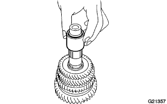
Install the output shaft spacer onto the output shaft.
| 17.
INSTALL 4TH DRIVEN GEAR |
|
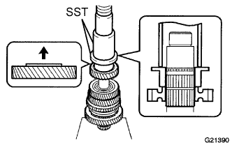
Using SST and a press, install the 4th driven gear onto the output shaft.
- SST
- 09223-00010
09316-60011
(09316-00021)
| 18.
INSTALL 5TH DRIVEN GEAR |
|
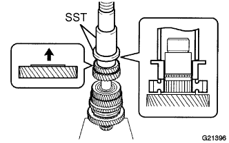
Using SST and a press, install the 5th driven gear onto the output shaft.
- SST
- 09223-00010
09316-60011
(09316-00021)
| 19.
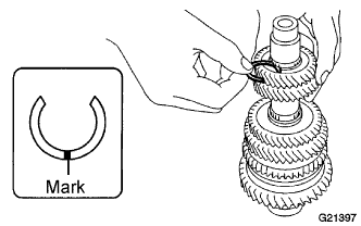
INSTALL COUNTER 5TH GEAR SHAFT SNAP RING |
|
Select a snap ring, using the table below, that makes the thrust clearance of the 5th driven gear less than 0.1 mm (0.0039 in.).
Mark
|
Thickness mm (in.)
|
Mark
|
Thickness mm (in.)
|
A
|
2.22 (0.0874)
|
F
|
2.52 (0.0992)
|
B
|
2.28 (0.0898)
|
G
|
2.58 (0.1016)
|
C
|
2.34 (0.0921)
|
H
|
2.64 (0.1039)
|
D
|
2.40 (0.0945)
|
J
|
2.70 (0.1063)
|
E
|
2.46 (0.0969)
|
-
|
-
|
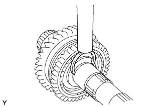
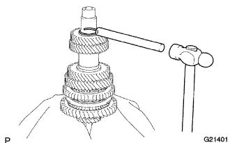
- Using a brass bar and hammer, tap the new snap ring onto the output shaft.
| 20.
INSTALL OUTPUT SHAFT REAR BEARING |
|
Using SST and a press, install the output shaft rear bearing onto the output shaft.
- SST
- 09612-22011