REMOVAL
Removal / installation · Vehicles built from Aug 2005
| 1. DISCONNECT CABLE FROM NEGATIVE BATTERY TERMINAL |
| 2. REMOVE INSTRUMENT PANEL FINISH PANEL END LH |

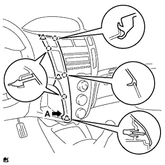  |
with CD player
Pull the instrument panel finish panel end LH rearward and disengage the 4 claws and 3 clips.
- NOTICE:
- To avoid damaging the radio receiver and the air conditioning panel, remove the instrument panel finish panel end without using any tool.
- HINT:
- Grip portion A of the instrument panel finish panel end and remove the instrument panel finish panel end from the lower side.
Disconnect the connector and remove the instrument panel finish panel end LH.
Except CD player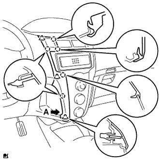
Pull the instrument panel finish panel end LH rearward and disengage the 5 claws and 3 clips.
- NOTICE:
- To avoid damaging the instrument cluster finish panel center and the air conditioning panel, remove the instrument panel finish panel end without using any tool.
- HINT:
- Grip portion A of the instrument panel finish panel end and remove the instrument panel finish panel end from the lower side.
Disconnect the connector and remove the instrument panel finish panel end LH.
| 3. REMOVE INSTRUMENT PANEL FINISH PANEL END RH |
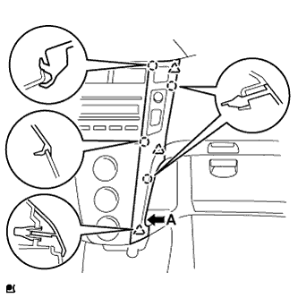 |
with CD player
Pull the instrument panel finish panel end RH and disengage the 4 claws and 3 clips.
- NOTICE:
- To avoid damaging the radio receiver and the air conditioning panel, remove the instrument panel finish panel end without using any tool.
- HINT:
- Grip portion A of the instrument panel finish panel end and remove the instrument panel finish panel end from the lower side.
Disconnect the connector and remove the instrument panel finish panel end RH.
Except CD player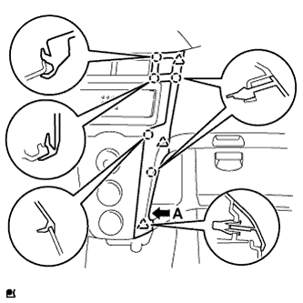
Pull the instrument panel finish panel end RH rearward and disengage the 5 claws and 3 clips.
- NOTICE:
- To avoid damaging the instrument cluster finish panel center and the air conditioning panel, remove the instrument panel finish panel end without using any tool.
- HINT:
- Grip portion A of the instrument panel finish panel end and remove the instrument panel finish panel end from the lower side.
Disconnect the connector and remove the instrument panel finish panel end RH.
| 4. REMOVE INSTRUMENT CLUSTER FINISH PANEL |
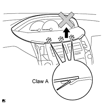 |
- NOTICE:
- Follow the procedure below to remove the instrument cluster finish panel. Claw A will break if the instrument cluster finish panel is raised carelessly.
Disengage the 2 claws and 5 clips.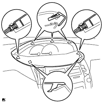
After removing the instrument panel finish panel end, insert your finger into the opening as shown, push the upper portion of the instrument cluster finish panel center and the 2 B claws of the instrument cluster finish panel, and then disengage the claws B.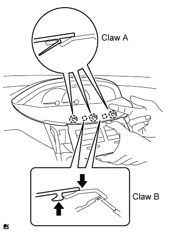
Disengage the 3 A claws and remove the instrument cluster finish panel.
| 5. REMOVE RADIO RECEIVER ASSEMBLY (w/ CD Player) |
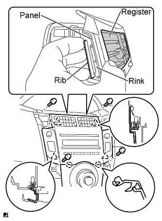 |
Remove the 4 screws.
Disengage the 2 claws and 4 clips and the radio receiver.
- NOTICE:
- Grip the rib portion of the radio receiver by hand to remove it.
- To avoid breakage of the radio receiver when removing it, do not apply excessive force to the register or pull out the rink or panel portions.
- Grip the rib portion of the radio receiver by hand to remove it.
Disconnect the connectors.
| 6. REMOVE INSTRUMENT CLUSTER FINISH PANEL CENTER SUB-ASSEMBLY (Except CD Player) |
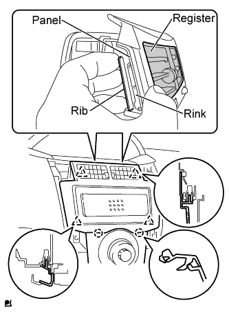 |
Disengage the 2 claws and 4 clips and the instrument cluster finish panel center.
- NOTICE:
- Grip the rib portion of the instrument cluster finish panel center by hand to remove it.
- To avoid breakage of the instrument cluster finish panel center when removing it, do not apply excessive force to the register or pull out the rink or panel portions.
- Grip the rib portion of the instrument cluster finish panel center by hand to remove it.
| 7. REMOVE AIR CONDITIONING PANEL ASSEMBLY |
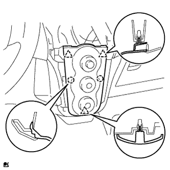 |
Disengage the 3 clips and 2 claws and remove the air conditioning panel.
Disconnect the 3 connectors and clamp.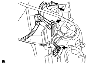
| 8. DISCONNECT AIR MIX DAMPER CONTROL CABLE SUB-ASSEMBLY |
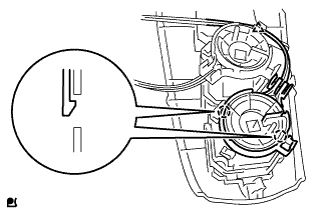 |
Disconnect the air mix control cable from the clamp.
Disengage the 2 claws and disconnect the air mix damper control cable.
| 9. DISCONNECT DEFROSTER DAMPER CONTROL CABLE SUB-ASSEMBLY |
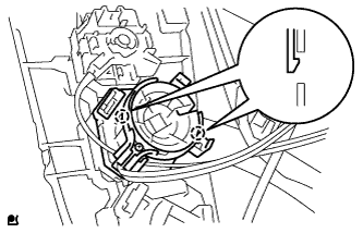 |
Disengage the 2 claws and disconnect the defroster damper control cable.
| 10. SEPARATE AIR INLET DAMPER CONTROL CABLE SUB-ASSEMBLY |
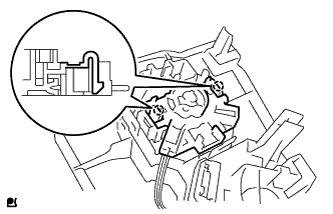 |
Disengage the 2 claws and disconnect the air inlet damper control cable.