TERMINALS OF ECU
System information · Vehicles built from Aug 2005
| CHECK CERTIFICATION ECU |
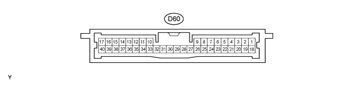

Disconnect the D60 ECU connector.
Measure the voltage and resistance of the wire harness side connector.
*1: LHDStandard Symbols (Terminal No.)
Wiring Color
Terminal Description
Condition
Specified Condition
+B1 (D60-1) - Body ground
B - Body ground
+B power supply
Always
10 to 14 V
IG (D60-18) - Body ground
BR - Body ground
Ignition power supply
Ignition switch off
Below 1 V
IG (D60-18) - Body ground
BR - Body ground
Ignition power supply
Ignition switch on (IG)
10 to 14 V
E (D60-17) - Body ground
W-B - Body ground
Ground
Always
Below 1 Ω
TSW1 (D60-3) - E (D60-17)
O*1 - W-B
W*2 - W-B
Door outside handle (driver side) lock switch signal
Switch released
10 kΩ or higher
TSW1 (D60-3) - E (D60-17)
O*1 - W-B
W*2 - W-B
Door outside handle (driver side) lock switch signal
Switch pressed in
Below 1 Ω
TSW2 (D60-4) - E (D60-17)
W*1 - W-B
O*2- W-B
Door outside handle (passenger side) lock switch signal
Switch released
10 kΩ or higher
TSW2 (D60-4) - E (D60-17)
W*1 - W-B
O*2- W-B
Door outside handle (passenger side) lock switch signal
Switch pressed in
Below 1 Ω
TSW5 (D60-7) - E (D60-17)
BR - W-B
Back door outside handle unlock switch signal
Switch released
10 kΩ or higher
TSW5 (D60-7) - E (D60-17)
BR - W-B
Back door outside handle unlock switch signal
Switch pressed in
Below 1 Ω
LIN (D60-10) - E (D60-17)
P - W-B
LIN line
Always
10 kΩ or higher
*2: RHD- If the result is not as specified, the wire harness connector may have a malfunction.
- If the result is not as specified, the wire harness connector may have a malfunction.
Reconnect the D60 ECU connector.
Measure the voltage of the connector.
*1: LHDStandard Symbols (Terminal No.)
Wiring Color
Terminal Description
Condition
Specified Condition
CLG1 (D60-33) - CG1B (D60-34)
GR - P
Door electrical key oscillator (driver side) sensor signal
All doors closed, all doors locked and Ignition switch off
Alternating between 5 V and below 1 V
CLG1 (D60-33) - CG1B (D60-34)
GR - P
Door electrical key oscillator (driver side) sensor signal
Door unlocked or door open
Below 1 V
SEN1 (D60-22) - E (D60-17)
V - W-B
Touch sensor detection signal
Outside door handle touched
10 to 14 V
SEN1 (D60-22) - E (D60-17)
V - W-B
Touch sensor detection signal
Outside door handle not touched
Below 1 V
SEL1 (D60-5) - E (D60-17)
R - W-B
Touch sensor activation control signal
Key at least 3 m (9.8 ft.) away from door
10 to 14 V
SEL1 (D60-5) - E (D60-17)
R - W-B
Touch sensor activation control signal
Key near to door
Below 1 V
CLG2 (D60-35) - CG2B (D60-36)
B - O
Door electrical key oscillator (passenger side) sensor signal
All doors closed, all doors locked and Ignition switch off
Alternating between 5 V and below 1 V
CLG2 (D60-35) - CG2B (D60-36)
B - O
Door electrical key oscillator (passenger side) sensor signal
Door unlocked or door open
Below 1 V
SEN2 (D60-23) - E (D60-17)
Y - W-B
Touch sensor detection signal
Outside door handle touched
10 to 14 V
SEN2 (D60-23) - E (D60-17)
Y - W-B
Touch sensor detection signal
Outside door handle not touched
Below 1 V
SEL2 (D60-6) - E (D60-17)
B - W-B
Touch sensor activation control signal
Key at least 3 m (9.8 ft.) away from door
10 to 14 V
SEL2 (D60-6) - E (D60-17)
B - W-B
Touch sensor activation control signal
Key near to door
Below 1 V
CLG5 (D60-11) - CG5B (D60-12)
LG - G
Indoor electrical key oscillator (front) sensor signal
30 seconds after driver door opened and closed, Ignition switch off
Alternating between 5 V and below 1 V
CLG5 (D60-11) - CG5B (D60-12)
LG - G
Indoor electrical key oscillator (front) sensor signal
Within 30 seconds driver door opened and closed, Ignition switch off
Below 1 V
CLG7 (D60-15) - CG7B (D60-16)
V - P
Indoor electrical key oscillator (rear) sensor signal
30 seconds after driver door opened and closed, Ignition switch off
Alternating between 5 V and below 1 V
CLG7 (D60-15) - CG7B (D60-16)
V - P
Indoor electrical key oscillator (rear) sensor signal
Within 30 seconds driver door opened and closed, Ignition switch off
Below 1 V
CLG8 (D60-31) - CG8B (D60-32)
LG - SB
Door electrical key oscillator (back door) sensor signal
Back door unlock switch OFF
Alternating between 5 V and below 1 V
CLG8 (D60-31) - CG8B (D60-32)
LG - SB
Door electrical key oscillator (back door) sensor signal
Back door unlock switch ON
Below 1 V
RC0 (D60-29) - E (D60-17)
L - W-B
Door control receiver power source
All doors closed, all doors locked and Ignition switch off
0 to 6 V
RC0 (D60-29) - E (D60-17)
L - W-B
Door control receiver power source
Door unlocked or door open
Below 1 V
RSSI (D60-39) - E (D60-17)
W - W-B
Door control receiver electric wave existence signal
All doors closed, all doors locked and Ignition switch off
0 to 5 V
RSSI (D60-39) - E (D60-17)
W - W-B
Door control receiver electric wave existence signal
Door unlocked or door open
Below 1 V
RDA (D60-38) - E (D60-17)
R - W-B
Door control receiver data input signal
All doors closed, all doors locked and Ignition switch off
Below 1 V
RDA (D60-38) - E (D60-17)
R - W-B
Door control receiver data input signal
Door unlocked or door open
Approx. 6 to 7 V
*2: RHD- If the result is not as specified, the ECU may have a malfunction.
- If the result is not as specified, the ECU may have a malfunction.
| CHECK DOOR ELECTRICAL KEY OSCILLATOR |
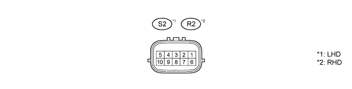
Disconnect the S2 or R2 door electrical key oscillator connector.
Measure the voltage and resistance of the wire harness side connector.
Standard (Front door LH side) Symbols (Terminal No.)
Wiring Color
Terminal Description
Condition
Specified Condition
+B (S2-1) - GND (S2-7)
Y - BR
+B power supply
Always
10 to 14 V
GND (S2-7) - Body ground
BR - Body ground
Ground
Always
Below 1 Ω
Front door RH side Symbols (Terminal No.)
Wiring Color
Terminal Description
Condition
Specified Condition
+B (R2-1) - GND (R2-7)
Y - BR
+B power supply
Always
10 to 14 V
GND (R2-7) - Body ground
BR - Body ground
Ground
Always
Below 1 Ω
- If the result is not as specified, the wire harness connector may have a malfunction.
- If the result is not as specified, the wire harness connector may have a malfunction.
Reconnect the S2 or R2 door electrical key oscillator connector.
Measure the voltage of the wire harness side connector.
Standard voltage (Front door LH side) Symbols (Terminal No.)
Wiring Color
Terminal Description
Condition
Specified Condition
CLG (S2-10) - GND (S2-7)
R - BR
Door electrical key oscillator sensor signal
All doors closed, all doors locked and Ignition switch off
Alternating between 5 V and below 1 V
CLG (S2-10) - GND (S2-7)
R - BR
Door electrical key oscillator sensor signal
Door unlocked or door open
Below 1 V
SEL (S2-4) - GND (S2-7)
O - BR
Touch sensor activation control signal
Key at least 3 m (9.8 ft.) away from door
10 to 14 V
SEL (S2-4) - GND (S2-7)
O - BR
Touch sensor activation control signal
Key near to door
Below 1 V
SENS (S2-6) - GND (S2-7)
V - BR
Touch sensor detection signal
Outside door handle touched
10 to 14 V
SENS (S2-6) - GND (S2-7)
V - BR
Touch sensor detection signal
Outside door handle not touched
Below 1 V
Front door RH side Symbols (Terminal No.)
Wiring Color
Terminal Description
Condition
Specified Condition
CLG (R2-10) - GND (R2-7)
R - BR
Door electrical key oscillator (driver side) sensor signal
All doors closed, all doors locked and Ignition switch off
Alternating between 5 V and below 1 V
CLG (R2-10) - GND (R2-7)
R - BR
Door electrical key oscillator (driver side) sensor signal
Door unlocked or door open
Below 1 V
SEL (R2-4) - GND (R2-7)
O - BR
Touch sensor activation control signal
Key at least 3 m (9.8 ft.) away from door
10 to 14 V
SEL (R2-4) - GND (R2-7)
O - BR
Touch sensor activation control signal
Key near to door
Below 1 V
SENS (R2-6) - GND (R2-7)
V - BR
Touch sensor detection signal
Outside door handle touched
10 to 14 V
SENS (R2-6) - GND (R2-7)
V - BR
Touch sensor detection signal
Outside door handle not touched
Below 1 V
- If the result is not as specified, the certification ECU, door electrical key oscillator or wire harness side connector may have a malfunction.
- If the result is not as specified, the certification ECU, door electrical key oscillator or wire harness side connector may have a malfunction.
| CHECK DOOR ELECTRICAL KEY OSCILLATOR (BACK DOOR) |

Measure the voltage of the wire harness side connector.
Standard voltage Symbols (Terminal No.)
Wiring Color
Terminal Description
Condition
Specified Condition
CLG5 (J37-1) - CLGB (J37-2)
LG - SB
Door electrical key oscillator (back door) sensor signal
Back door unlock switch OFF
Alternating between 5 V and below 1 V
CLG5 (J37-1) - CLGB (J37-2)
LG - SB
Door electrical key oscillator (back door) sensor signal
Back door unlock switch ON
Below 1 V
- If the result is not as specified, the certification ECU, door electrical key oscillator (back door) or wire harness side connector may have a malfunction.
- If the result is not as specified, the certification ECU, door electrical key oscillator (back door) or wire harness side connector may have a malfunction.
| CHECK MAIN BODY ECU |
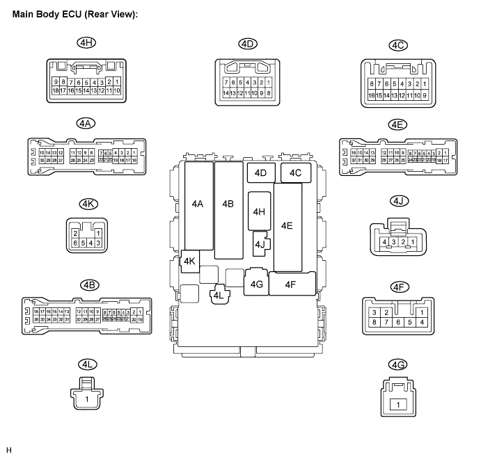
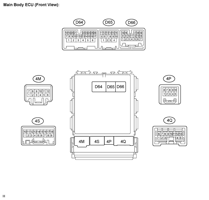
Disconnect the 4B, 4D, 4E, and 4S ECU (vehicle rear side) connectors.
Disconnect the D64, D65, D66, and 4S ECU (vehicle front side) connectors.
Measure the voltage and resistance of the wire harness side connectors.
Standard Symbols (Terminal No.)
Wiring Color
Terminal Description
Condition
Specified Condition
BECU (4B-30) - Body ground
L - Body ground
+B power supply
Always
10 to 14 V
AM1 (D65-1) - Body ground
O - Body ground
+B power supply
Always
10 to 14 V
AM2 (D64-6) - Body ground
SB - Body ground
+B power supply
Always
10 to 14 V
TR+ (D64-1) - Body ground
O - Body ground
Back door signal
Always
Below 1 Ω
IG (4S-7) - Body ground
R - Body ground
IG2 signal
Ignition switch on (IG)
10 to 14 V
IG (4S-7) - Body ground
R - Body ground
IG2 signal
Ignition switch off
Below 1 V
ACC (4S-6) - Body ground
GR - Body ground
ACC signal
Ignition switch on (ACC)
10 to 14 V
GND1(4E-17) - Body ground
W-B - Body ground
Ground
Always
Below 1 Ω
GND2(D65-4) - Body ground
W-B - Body ground
Ground
Always
Below 1 Ω
CANH (D66-15) - Body ground
R - Body ground
CAN communication line
Always
10 kΩ or higher
CANL (D66-16) - Body ground
W - Body ground
CAN communication line
Always
10 kΩ or higher
LIN1(4D-9) - Body ground
P - Body ground
LIN communication line
Always
10 kΩ or higher
BDSU(D64-12) - Body ground
Y - Body ground
Back door outside handle lock switch signal
Switch released
10 kΩ or higher
BDSU(D64-12) - Body ground
Y - Body ground
Back door outside handle lock switch signal
Switch pressed in
Below 1 Ω
- If the result is not as specified, the wire harness connector may have a malfunction.
- If the result is not as specified, the wire harness connector may have a malfunction.
Reconnect the ECU connectors.
Measure the voltage of the connectors.
Standard voltage Symbols (Terminal No.)
Wiring Color
Terminal Description
Condition
Specified Condition
DCTY (4A-21) - Body ground
R - Body ground
Driver side door courtesy switch input
Driver side door closed
10 to 14 V
DCTY (4A-21) - Body ground
R - Body ground
Driver side door courtesy switch input
Driver side door open
Below 1 V
PCTY (4A-24) - Body ground
L - Body ground
Passenger side door courtesy switch input
Passenger side door closed
10 to 14 V
PCTY (4A-24) - Body ground
L - Body ground
Passenger side door courtesy switch input
Passenger side door open
Below 1 V
RRCY (4A-20) - Body ground
L - Body ground
Rear RH door courtesy switch input
Rear RH door closed
10 to 14 V
RRCY (4A-20) - Body ground
L - Body ground
Rear RH door courtesy switch input
Rear RH door open
Below 1 V
RRCY (4A-5) - Body ground
G - Body ground
Rear LH door courtesy switch input
Rear LH door closed
10 to 14 V
RRCY (4A-5) - Body ground
G - Body ground
Rear LH door courtesy switch input
Rear LH door open
Below 1 V
BCTY (4A-7) - Body ground
SB- Body ground
Back door courtesy switch input
Back side door closed
10 to 14 V
BCTY (4A-7) - Body ground
SB- Body ground
Back door courtesy switch input
Back side door open
Below 1 V
HAZ (4S-17) - Body ground
B- Body ground
Hazard warning light signal
Answer-back ON
Pulse generation
HAZ (4S-17) - Body ground
B- Body ground
Hazard warning light signal
Answer-back OFF
10 to 14 V
- If the result is not as specified, the main body ECU may have a malfunction.
- If the result is not as specified, the main body ECU may have a malfunction.