DISASSEMBLY
Removal / installation · Vehicles built from Nov 2005
| 1. REMOVE SHIFT STROKE SENSOR |
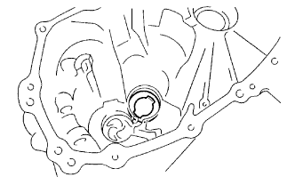
| 2. REMOVE CLUTCH RELEASE FORK |
| 3. REMOVE CLUTCH RELEASE FORK LEVER SHAFT OIL SEAL |
| 4. INSPECT NEUTRAL POSITION |

Remove the plug from the shift and select actuator.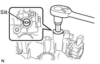

Look through the plug and check that the slit of the shift and select shaft is in the position shown in the illustration.
If not, turn it with a screwdriver.
| 5. REMOVE LOCK BALL ASSEMBLY NO.1 |
Using an 18 mm socket wrench, remove the lock ball assembly from the transaxle case.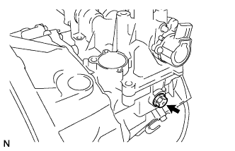
| 6. REMOVE PARK/NEUTRAL POSITION SWITCH ASSEMBLY |
Using SST, remove the park/neutral position switch with the gasket from the transaxle case.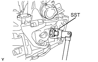
- SST
- 09817-16011
| 7. REMOVE SHIFT AND SELECT ACTUATOR ASSEMBLY |
Remove the 6 bolts.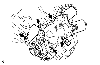
Tap the actuator flange with a plastic hammer to remove it.
| 8. REMOVE BACK-UP LIGHT SWITCH ASSEMBLY |
Using SST, remove the back-up light switch with the gasket from the transaxle case.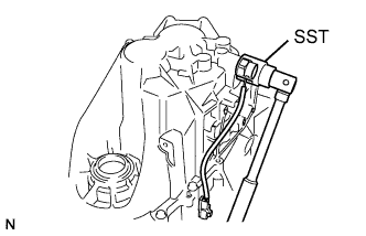
- SST
- 09817-16011
| 9. REMOVE TRANSMISSION REVOLUTION SENSOR |
Remove the bolt and transmission case protector.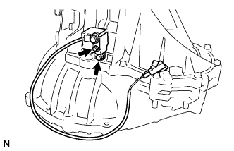
Remove the bolt and transmission revolution sensor.
Using a small screwdriver, remove the O-ring from the transmission revolution sensor.
| 10. REMOVE REVERSE IDLER GEAR SHAFT BOLT |
Remove the reverse idler gear shaft lock bolt with the gasket from the transmission case.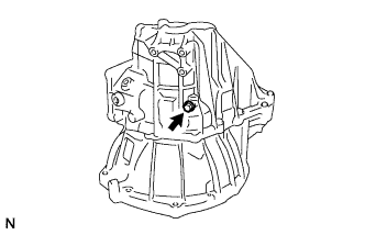
| 11. REMOVE MANUAL TRANSMISSION CASE |
Remove the 13 bolts.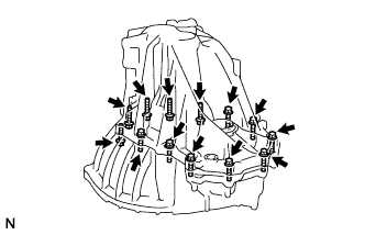
Using a brass bar and hammer, tap the projection of the transmission case and remove the case.
Remove the shim from the transmission case.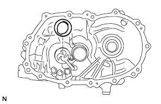
| 12. REMOVE SHIFT HEAD SET SLOTTED SPRING PIN |
Using a pin punch and hammer, drive out the 2 slotted spring pins out of gear shift heads No. 1 and No. 3.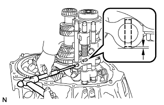
| 13. REMOVE GEAR SHIFT FORK SHAFT NO.1 |
Remove the set bolt from gear shift fork No. 1.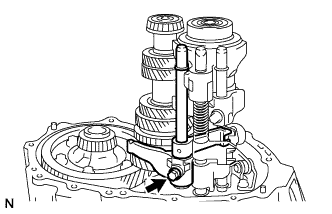
Pull out gear shift fork shaft No.1 and the snap ring from the transaxle case.
Remove gear shift head No.1 and gear shift fork No. 1.
Using 2 screwdrivers and a hammer, remove the snap ring from gear shift fork shaft No. 1.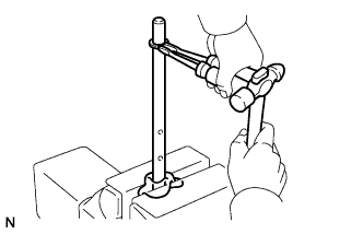
| 14. REMOVE GEAR SHIFT FORK SHAFT NO.3 |
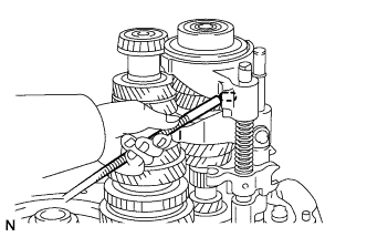 |
Using a magnetic finger, remove the straight pin from gear shift fork No. 3.
Using 2 screwdrivers and a hammer, remove the 2 snap rings from gear shift fork shaft No. 3.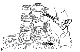
Cover gear shift fork shaft No.3 with a piece of cloth gear shift fork shaft No. 3 at the upper edge with pliers as shown in the illustration, and pull gear shift fork shaft No. 3 out of the transaxle case to remove gear shift fork No. 3, compression spring and gear shift head No. 3.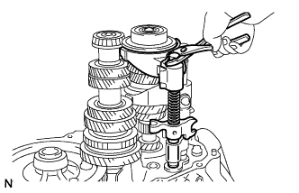
| 15. REMOVE REVERSE IDLER GEAR SHAFT |
Remove the reverse idler gear shaft from the transaxle case.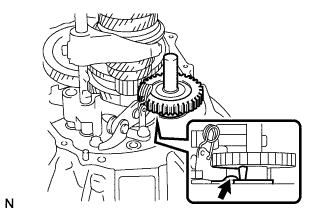
| 16. REMOVE REVERSE SHIFT ARM BRACKET ASSEMBLY |
Remove the 2 bolts and reverse shift arm bracket from the transaxle case.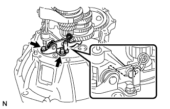
| 17. REMOVE GEAR SHIFT FORK SHAFT NO.2 |
Using a magnetic finger, remove the straight pin from the reverse shift fork.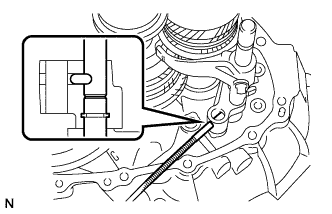
Shift hub sleeve No. 2 into the 3rd gear, as shown.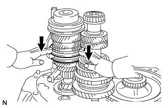
Remove the set bolt from gear shift fork No. 2.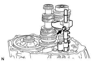
Pull out gear shift fork snap rings, gear shift fork and the reverse shift fork from the transaxle case.
Using 2 screwdrivers and a hammer, remove the snap ring from gear shift fork shaft No. 2.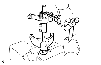
Remove the reverse shift fork from gear shift fork shaft No. 2.
Using 2 screwdrivers and a hammer, remove the snap ring from gear shift fork shaft No. 2.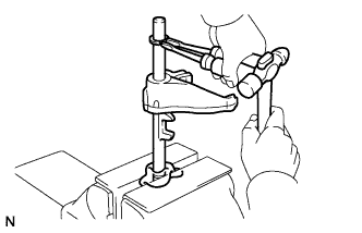
Remove gear shift fork No. 2 from gear shift fork shaft No. 2.
| 18. REMOVE INPUT SHAFT |
Remove the input shaft assembly from the manual transaxle case.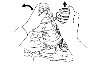
| 19. REMOVE OUTPUT SHAFT |
Remove the output shaft assembly from the manual transaxle case.
| 20. REMOVE FRONT DIFFERENTIAL CASE |
Remove the differential case assembly from the front transaxle case.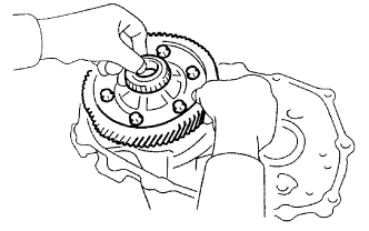
| 21. REMOVE OIL RECEIVER PIPE NO. 2 |
Remove the oil receiver pipe No. 2 from the manual transmission case.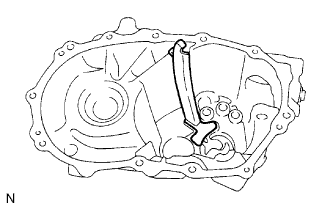
- NOTICE:
- Do not damage oil receiver pipe No. 2.
| 22. REMOVE TRANSMISSION MAGNET |
Remove the transmission magnet from the front transaxle case.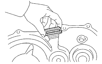
| 23. REMOVE FRONT TRANSAXLE CASE OIL SEAL |
Using a screwdriver, remove the front transaxle case oil seal.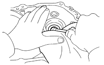
| 24. REMOVE OUTPUT SHAFT FRONT BEARING |
Using SST, remove the output shaft front bearing (outer race) from the front transaxle case.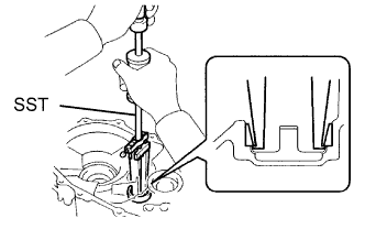
- SST
- 09308-00010
| 25. REMOVE OUTPUT SHAFT COVER |
Remove the output shaft cover from the front transaxle case.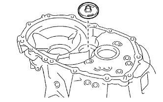
| 26. REMOVE TRANSMISSION CASE OIL SEAL |
Using a screwdriver, remove the transmission case oil seal.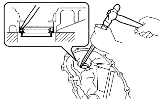
| 27. REMOVE FR DIFFERENTIAL CASE REAR TAPERED ROLLER BEARING |
Using SST, remove the front differential case rear tapered roller bearing and the shim.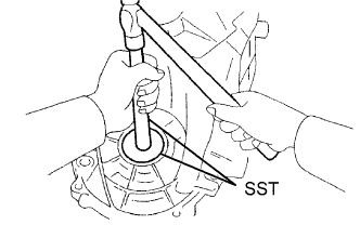
- SST
- 09950-60010
(09951-00560)
09950-70010 (09951-07200)
| 28. REMOVE TRANSAXLE CASE OIL SEAL |
Using a screwdriver, remove the transaxle case oil seal from the front transaxle case.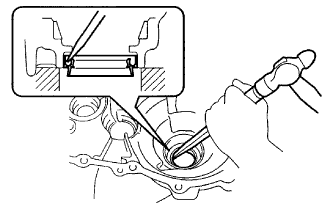
| 29. REMOVE FR DIFFERENTIAL CASE FRONT TAPERED ROLLER BEARING |
Using a brass bar and hammer, remove the front differential case front tapered roller bearing.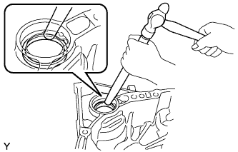
| 30. REMOVE INPUT SHAFT REAR BEARING SHIM |
Remove the input shaft rear bearing shim.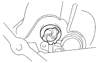
| 31. REMOVE OUTPUT SHAFT REAR BEARING |
Using SST, remove the output shaft rear bearing.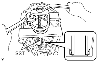
- SST
- 09527-30010
09612-65014 (09612-01030, 09612-01050)
| 32. REMOVE OUTPUT SHAFT REAR BEARING SHIM |
Remove the output shaft rear bearing shim.