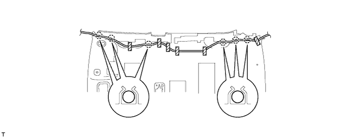
REMOVAL
Removal / installation · Vehicles built from Jan 2006
- CAUTION:
- Some of these service operations affect the SRS airbag system. Read the precautionary notices concerning the SRS airbag system before servicing (Click here).
| 1. DISCONNECT CABLE FROM NEGATIVE BATTERY TERMINAL |

- CAUTION:
- Wait for at least 90 seconds after disconnecting the cable to prevent the airbag from working.
| 2. REMOVE REAR SEAT CUSHION COVER PAD SUB-ASSEMBLY |
for 60/40 Split Seat Type:
Remove the rear seat cushion cover pad sub-assembly (Click here).
for Fixed Seat Type:
Remove the rear seat cushion cover pad sub-assembly (Click here).
| 3. REMOVE REAR SEATBACK ASSEMBLY RH (for 60/40 Split Seat Type) |
Remove the rear seat outer belt from the rear seat shoulder belt guide.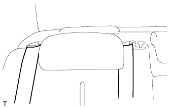

for 3 Point Type Rear Center Seat Belt:
Remove the rear center seat outer belt from the rear center seat shoulder belt guide.
Pull the rear seatback lock release button and tilt the rear seatback forward.
Using a clip remover, remove the 2 clips and the rear seatback cover.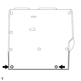
Remove the 2 bolts, the 2 hooks and the rear seatback.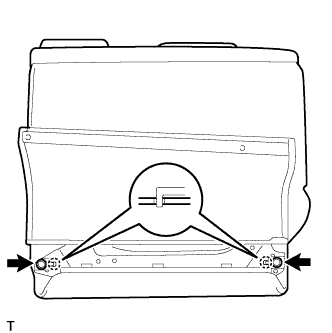
| 4. REMOVE REAR SEATBACK ASSEMBLY LH (for 60/40 Split Seat Type) |
Remove the rear seat outer belt from the rear seat shoulder belt guide.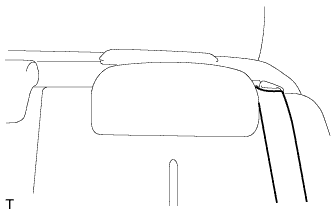
Pull the rear seatback lock release button and tilt the rear seatback forward.
Using a clip remover, remove the 2 clips and the rear seatback cover.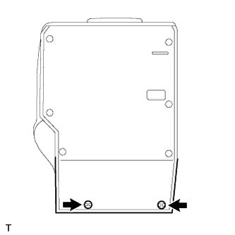
Remove the 2 bolts, the 2 hooks and the rear seatback.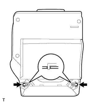
| 5. REMOVE REAR SEATBACK ASSEMBLY (for Fixed Seat Type) |
Remove the rear seat outer belt from the rear seat shoulder belt guide.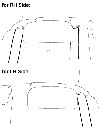
- HINT:
- Use the same procedure for both sides.
for 3 Point Type Rear Center Seat belt:
Remove the rear center seat outer belt from the rear center seat shoulder belt guide.
Remove the 3 bolts.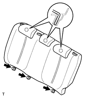
Disengage the 3 hooks and remove the rear seatback.
| 6. REMOVE LUGGAGE COMPARTMENT FLOOR MAT (for 60/40 Split Seat Type) |
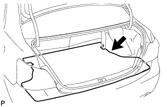 |
Remove the luggage compartment floor mat.
| 7. REMOVE SPARE WHEEL COVER ASSEMBLY (for 60/40 Split Seat Type) |
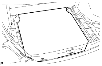 |
Remove the spare wheel cover.
| 8. REMOVE LUGGAGE COMPARTMENT TRIM INNER PAD (for 60/40 Split Seat Type) |
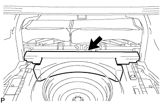 |
Remove the luggage compartment trim inner pad.
| 9. REMOVE FRONT DOOR SCUFF PLATE RH |
Disengage the 11 claws and remove the front door scuff plate.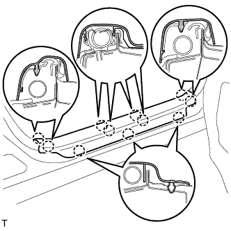
| 10. REMOVE FRONT DOOR SCUFF PLATE LH |
- HINT:
- Use the same procedure as for the RH side.
| 11. REMOVE COWL SIDE TRIM BOARD RH |
Disengage the claw and the stud bolt and remove the cowl side trim board.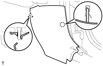
| 12. REMOVE COWL SIDE TRIM BOARD LH |
- HINT:
- Use the same procedure as for the RH side.
| 13. REMOVE FRONT DOOR OPENING TRIM WEATHERSTRIP RH |
Remove the front door opening trim weatherstrip.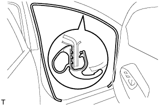
| 14. REMOVE FRONT DOOR OPENING TRIM WEATHERSTRIP LH |
- HINT:
- Use the same procedure as for the RH side.
| 15. REMOVE REAR DOOR SCUFF PLATE RH |
Disengage the 7 claws and remove the rear door scuff plate.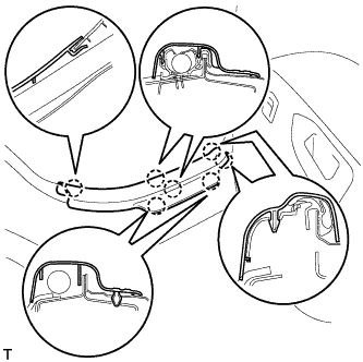
| 16. REMOVE REAR DOOR SCUFF PLATE LH |
- HINT:
- Use the same procedure as for the RH side.
| 17. REMOVE REAR DOOR OPENING TRIM WEATHERSTRIP RH |
Remove the rear door opening trim weatherstrip.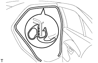
| 18. REMOVE REAR DOOR OPENING TRIM WEATHERSTRIP LH |
- HINT:
- Use the same procedure as for the RH side.
| 19. REMOVE REAR SEAT SIDE COVER RH |
Disengage the 2 clips and the 4 claws and remove the rear seat side cover.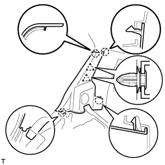
| 20. REMOVE REAR SEAT SIDE COVER LH |
- HINT:
- Use the same procedure as for the RH side.
| 21. REMOVE ROOF SIDE INNER GARNISH RH |
w/ Curtain Shield Airbag: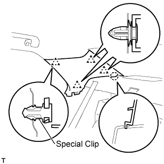
- NOTICE:
- Replace the special clip with a new one when the roof side inner garnish is removed.
Disengage the 4 clips and the claw and remove the roof side inner garnish.
w/o Curtain Shield Airbag: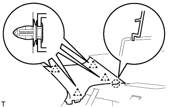
Disengage the 4 clips and the claw and remove the roof side inner garnish.
| 22. REMOVE ROOF SIDE INNER GARNISH LH |
- HINT:
- Use the same procedure as for the RH side.
| 23. REMOVE CENTER PILLAR LOWER GARNISH RH |
Disengage the 3 claws and 2 clips and remove the center pillar lower garnish.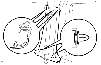
| 24. REMOVE CENTER PILLAR LOWER GARNISH LH |
- HINT:
- Use the same procedure as for the RH side.
| 25. REMOVE SEAT BELT ANCHOR COVER CAP |
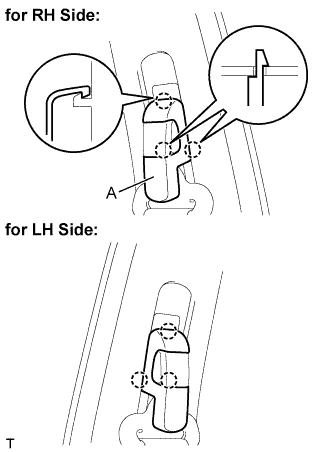 |
- HINT:
- Use the same procedure for both sides.
Pull portion A, shown in the illustration, toward you, remove the 2 claws on the lower side followed by the claw on the upper side. Then remove the seat belt anchor cover cap.
| 26. REMOVE FRONT SEAT OUTER BELT ASSEMBLY RH |
Remove the bolt and the through anchor.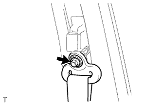
| 27. REMOVE FRONT SEAT OUTER BELT ASSEMBLY LH |
- HINT:
- Use the same procedure as for the RH side.
| 28. REMOVE CENTER PILLAR UPPER GARNISH RH |
Disengage the 2 clips and 2 hooks and remove the center pillar upper garnish.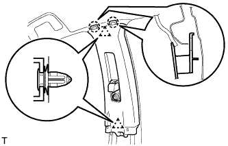
| 29. REMOVE CENTER PILLAR UPPER GARNISH LH |
- HINT:
- Use the same procedure as for the RH side.
| 30. REMOVE FRONT PILLAR GARNISH RH |
w/ Curtain Shield Airbag: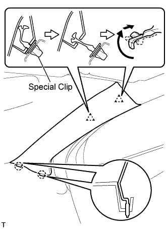
- NOTICE:
- Install a protective cover onto the curtain shield airbag as soon as the front pillar garnish is removed.
- Replace the special clip with a new one when the front pillar garnish is removed.
- Install a protective cover onto the curtain shield airbag as soon as the front pillar garnish is removed.
Disengage the 2 clips and the 2 claws and remove the front pillar garnish.
w/o Curtain Shield Airbag: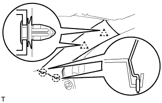
Disengage the 2 clips and the 2 claws and remove the front pillar garnish.
Disconnect the antenna connector.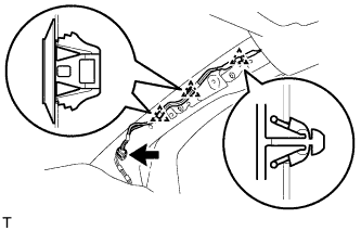
Using a clip remover, remove the 3 clamps.
w/ Curtain Shield Airbag: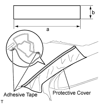
Completely cover the curtain shield airbag with a piece of cloth or nylon and fix the ends of the fabric with adhesive tape, as shown in the illustration.
- Protective cover size:
Area
Measurement
a
700 mm (27.56 in.)
b
120 mm (4.72 in.)
| 31. REMOVE FRONT PILLAR GARNISH LH |
w/ Curtain Shield Airbag: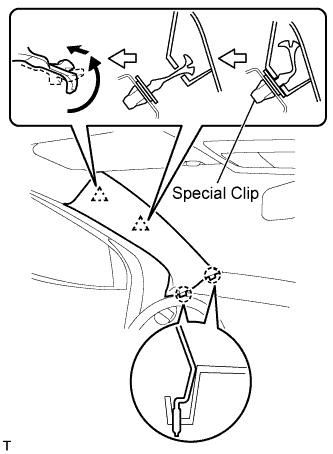
- NOTICE:
- Install a protective cover onto the curtain shield airbag as soon as the front pillar garnish is removed.
- Replace the special clip with a new one when the front pillar garnish is removed.
- Install a protective cover onto the curtain shield airbag as soon as the front pillar garnish is removed.
Disengage the 2 clips and the 2 claws and remove the front pillar garnish.
w/o Curtain Shield Airbag: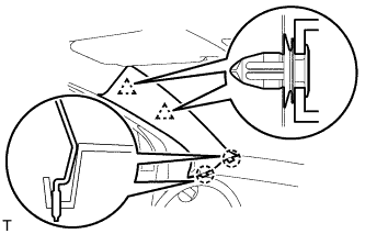
Disengage the 2 clips and the 2 claws and remove the front pillar garnish.
Using a clip remover, remove the 4 clamps.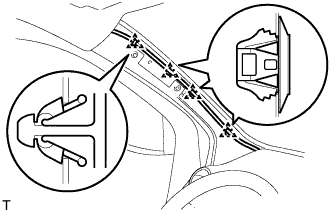
w/ Curtain Shield Airbag: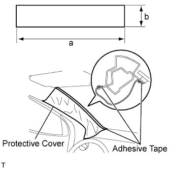
Completely cover the curtain shield airbag with a piece of cloth or nylon and fix the ends of the fabric with adhesive tape, as shown in the illustration.
- Protective cover size:
Area
Measurement
a
700 mm (27.56 in.)
b
120 mm (4.72 in.)
| 32. REMOVE INSTRUMENT PANEL LOWER CENTER FINISH PANEL |
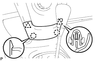 |
Disengage the 2 claws and 2 clips and remove the instrument panel finish panel lower center.
| 33. REMOVE INSTRUMENT PANEL FINISH PANEL END RH |
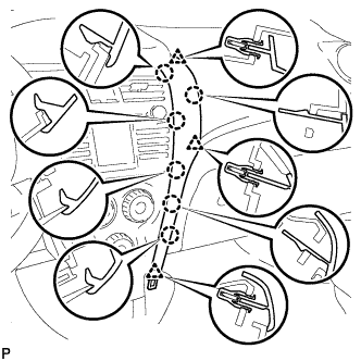 |
Disengage the 6 claws and 3 clips and remove the instrument panel finish panel end RH.
| 34. REMOVE INSTRUMENT PANEL FINISH PANEL END LH |
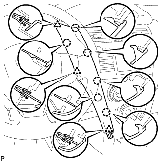 |
Disengage the 6 claws and 3 clips and remove the instrument panel finish panel end LH.
| 35. REMOVE INSTRUMENT CLUSTER FINISH PANEL |
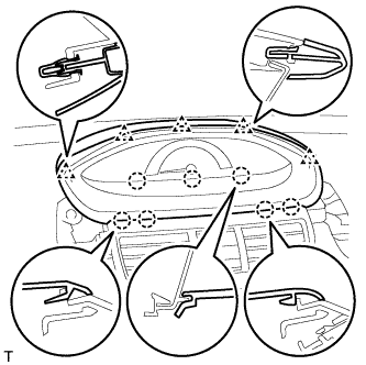 |
Disengage the 4 claws and 5 clips and remove the instrument cluster finish panel.
| 36. REMOVE COMBINATION METER ASSEMBLY |
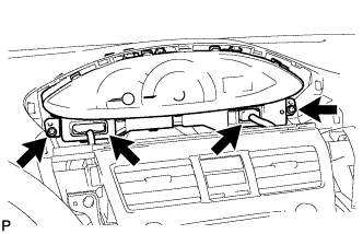 |
Disconnect the 2 connectors.
Remove the 2 screws and pull the combination meter rearward to remove it.
| 37. REMOVE GLOVE COMPARTMENT DOOR ASSEMBLY |
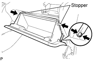 |
Disengage the claw and separate the glove compartment door stopper from the glove compartment door.
Slightly flex the upper part of the glove compartment door assembly to release the 2 stoppers and open the glove compartment door until it becomes horizontal.
Pull the glove compartment door assembly out horizontally to disengage the hinge portion and remove the glove compartment door.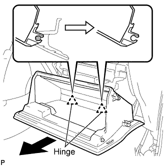
- NOTICE:
- Pull the glove compartment door out horizontally, otherwise, installation failure caused by excessive play around the hinge portion will result.
| 38. REMOVE UPPER INSTRUMENT PANEL SUB-ASSEMBLY |
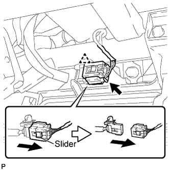 |
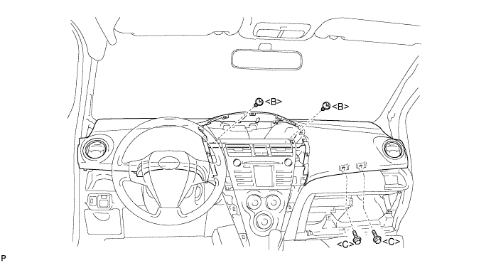
Slide the slider and disconnect the passenger airbag connector.
Disconnect the clamp.
Remove the 2 <C> bolts and 2 <B> screws.
Disengage the 7 clips by lifting the rear side of the instrument panel up.
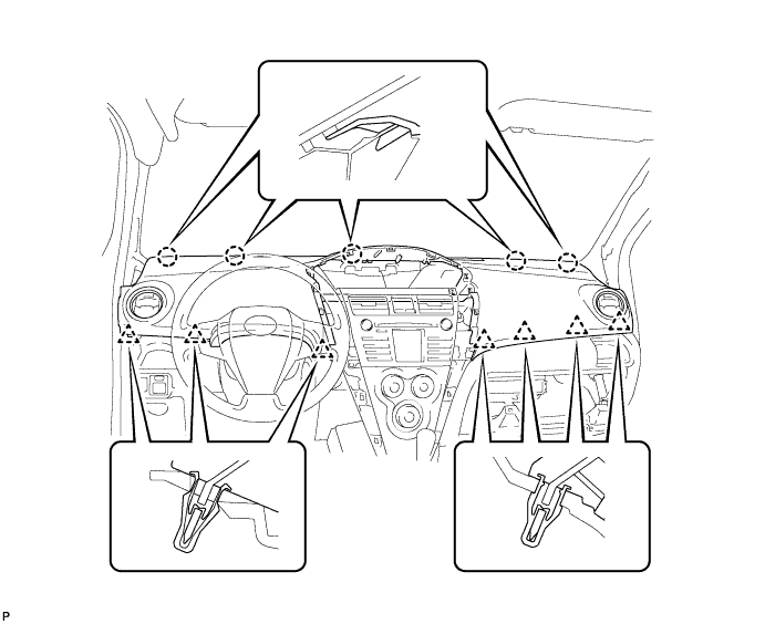
While lifting the instrument panel, slide it toward the rear of the vehicle. Disengage the 5 claws from the front side of the instrument panel and remove the instrument panel.
| 39. REMOVE INSTRUMENT CLUSTER CENTER FINISH PANEL SUB-ASSEMBLY (for LHD) |
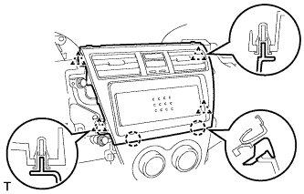 |
Disengage the 2 claws and 4 clips and remove the instrument cluster panel center.
| 40. REMOVE RADIO RECEIVER ASSEMBLY (for LHD) |
Remove the 4 bolts and the radio receiver.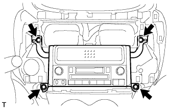
Disconnect the plug.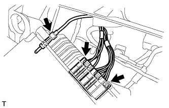
Disconnect the 2 radio connectors.
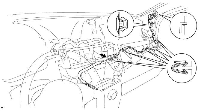
| 41. REMOVE ANTENNA CORD SUB-ASSEMBLY |
for LHD:
Remove the bolt, the hook and the bracket.
Using a clip remover, remove the clamp.
Disconnect the antenna amplifier connector.
Remove the 5 clamps and the antenna cord.
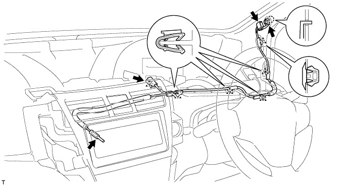
for RHD:
Remove the bolt, the hook and the bracket.
Using a clip remover, remove the clamp.
Disconnect the antenna amplifier connector.
Disconnect the plug.
Remove the 4 clamps and the antenna cord.
| 42. REMOVE ROOF HEADLINING SERVICE HOLE COVER |
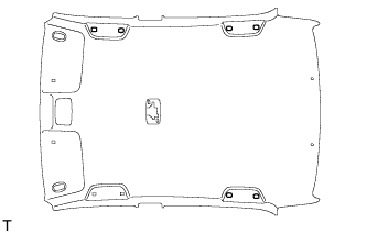 |
- HINT:
- The number of the roof headlining service hole covers varies with the specifications.
Using a clip remover with its tip wrapped in protective tape, remove the 2 roof headlining service hole covers.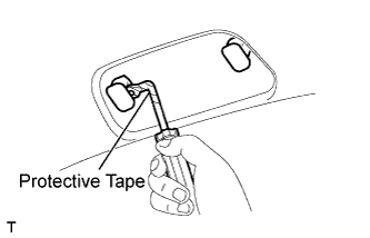
| 43. REMOVE ASSIST GRIP COVER |
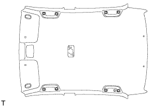 |
- HINT:
- The number of the assist grip covers varies with the specifications.
Using a screwdriver with its tip wrapped in protective tape, disengage the 2 claws and remove the assist grip cover.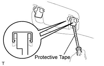
| 44. REMOVE ASSIST GRIP SUB-ASSEMBLY |
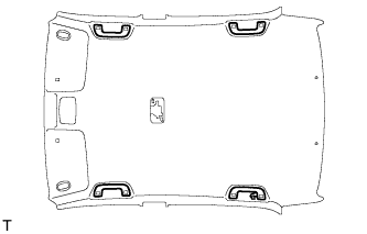 |
- HINT:
- The number of the assist grips varies with the specifications.
Disengage the 2 springs and remove the assist grip.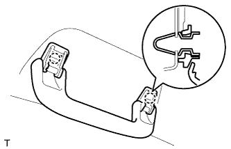
| 45. REMOVE VISOR ASSEMBLY RH |
Using a screwdriver with its tip wrapped in protective tape, disengage the 4 claws and remove the visor bracket cover.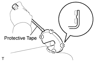
Remove the visor shaft from the visor holder.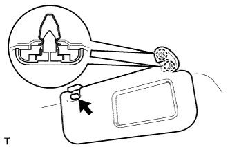
Disengage the 2 springs and remove the visor.
| 46. REMOVE VISOR ASSEMBLY LH |
- HINT:
- Use the same procedure as for the RH side.
| 47. REMOVE VISOR HOLDER RH |
Disengage the 2 claws by turning the visor counterclockwise between 60 to 120° and remove the visor holder.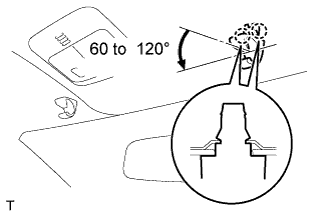
- HINT:
- The claw may be damaged during removal. However, it is reusable because this does not effect its function.
| 48. REMOVE VISOR HOLDER LH |
- HINT:
- Use the same procedure as for the RH side.
| 49. REMOVE ROOM LIGHT ASSEMBLY |
Using a screwdriver with its tip wrapped in protective tape, disengage the 4 claws and remove the room light lens.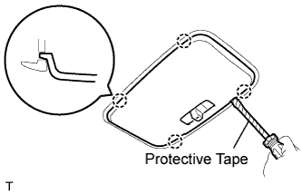
Using a screwdriver with its tip wrapped in protective tape, disengage the 2 claws and remove the cover.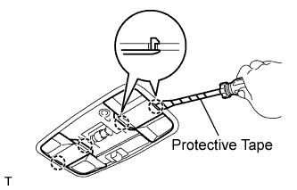
- HINT:
- Use the same procedure for both sides.
Using a screwdriver with its tip wrapped in protective tape, disengage the 4 claws and remove the room light.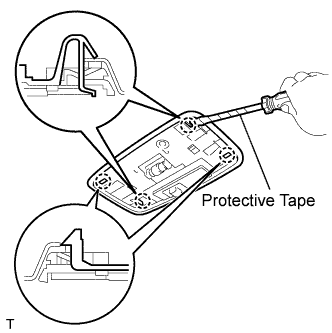
Remove the roof wire from the claw of the room light.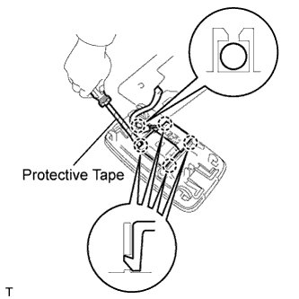
Using a screwdriver with its tip wrapped in protective tape, disengage the 4 claws and disconnect the room light switch base.
| 50. REMOVE MAP LIGHT ASSEMBLY |
Using a moulding remover, disengage the 4 claws and remove the map light.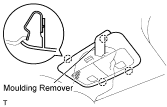
Disconnect the map light connector.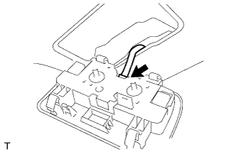
| 51. REMOVE ROOF HEADLINING ASSEMBLY |
Using a clip remover, remove the clamp.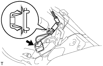
Disconnect the antenna cord connector.
w/ Curtain Shield Airbag: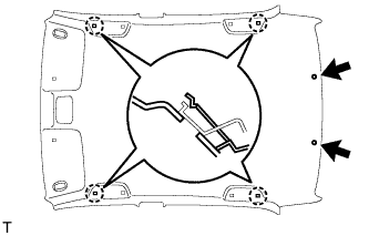
Using a clip remover, remove the 2 clips.
Disengage the 4 hooks and remove the roof headlining.
w/o Curtain Shield Airbag: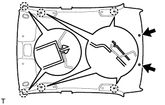
Using a clip remover, remove the 2 clips.
Disengage the 2 claws and 4 hooks and remove the roof headlining.
| 52. REMOVE NO. 2 ANTENNA CORD SUB-ASSEMBLY |
w/ Curtain Shield Airbag:
Remove the 8 pieces of tape.
Remove the No. 2 antenna cord from the 4 claws of the front and rear side real spacers.
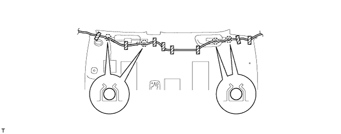
w/ Curtain Shield Airbag:
Remove the 6 pieces of tape.
Remove the No. 2 antenna cord from the 6 claws of the front and rear side real spacers.