INSTALLATION
Removal / installation · Vehicles built from Aug 2005
| 1. INSTALL PARK/NEUTRAL POSITION SWITCH ASSEMBLY |

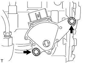  |
Install the park/neutral position switch assembly onto the manual transaxle.
Provisionally install the 2 bolts.
Replace the lock plate with a new one and tighten the manual valve shaft nut.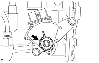
- Torque:
- 6.9 N*m{ 70 kgf*cm , 61 in.*lbf }
Provisionally install the control shaft lever.
Turn the lever counterclockwise until it stops, then turn it clockwise 2 notches.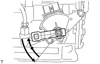
Remove the control shaft lever.
Align the groove with the neutral basic line.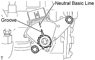
Hold the switch in this position and tighten the 2 bolts.
- Torque:
- 5.4 N*m{ 55 kgf*cm , 48 in.*lbf }
Using a screwdriver, stake the nut with the lock plate.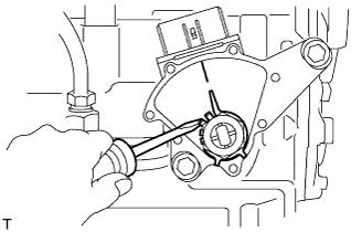
Install the control shaft lever with the nut and washer.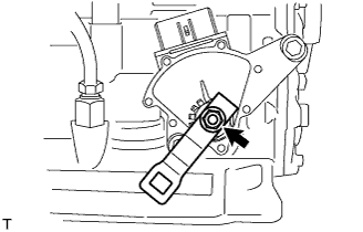
- Torque:
- 13 N*m{ 130 kgf*cm , 9 ft.*lbf }
Connect the connector to the park/neutral position switch assembly.
| 2. INSTALL TRANSMISSION CONTROL CABLE ASSEMBLY |
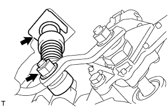 |
Install the transmission control cable onto the control shaft lever with the nut.
- Torque:
- 12 N*m{ 122 kgf*cm , 9 ft.*lbf }
Install the transmission control cable into the bracket with the new clip.
| 3. CONNECT CABLE TO NEGATIVE BATTERY TERMINAL |
- Torque:
- 5.4 N*m{ 55 kgf*cm , 48 in.*lbf }
| 4. INSPECT SHIFT LEVER POSITION |
When shifting the lever from P to the R position with the ignition switch ON and the brake pedal depressed, make sure that the shift lever moves smoothly and moves correctly into position.
Start the engine and make sure that the vehicle moves forward when shifting the lever from N to the D position and moves rearward when shifting the lever to the R position.
If the operation cannot be performed as specified, inspect the park/neutral position switch assembly and check the shift lever assembly installation condition.
| 5. ADJUST SHIFT LEVER POSITION |
Shift the shift lever to the N position.
Slide the adjuster case cover in the direction shown in the illustration and pull out the lock piece.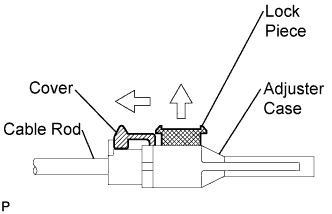
Gently pull the cable rod toward the rear of the vehicle by hand to pull the cable taut.
Press the lock piece into the adjuster case and lock it.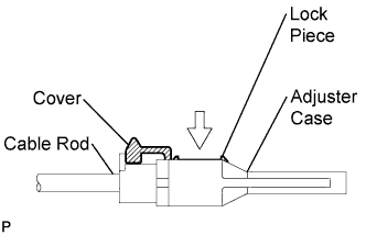
Slide the cover in the direction shown in the illustration.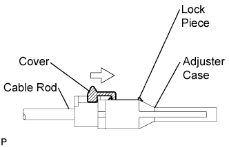
- NOTICE:
- Slide the cover past the protrusion of the lock piece.
Inspect the operation after the adjustment.
| 6. INSPECT PARK/NEUTRAL POSITION SWITCH ASSEMBLY |
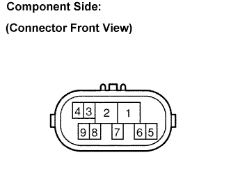 |
Disconnect the park/neutral position switch connector.
Measure the resistance with the shift lever in each position.
- Standard resistance:
Shift Position
Tester Connection
Specified Condition
P
2 - 6 and 4 - 5
Below 1 Ω
Except P
↑
10 kΩ or higher
R
2 - 1
Below 1 Ω
Except R
↑
10 kΩ or higher
N
2 - 9 and 4 - 5
Below 1 Ω
Except N
↑
10 kΩ or higher
D and 3
2 - 7
Below 1 Ω
Except D and 3
↑
10 kΩ or higher
2
2 - 3
Below 1 Ω
Except 2
↑
10 kΩ or higher
L
2 - 8
Below 1 Ω
Except L
↑
10 kΩ or higher
| 7. INSTALL ENGINE UNDER COVER LH |