Removal / installation · Vehicles built from Nov 2006
1.
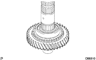
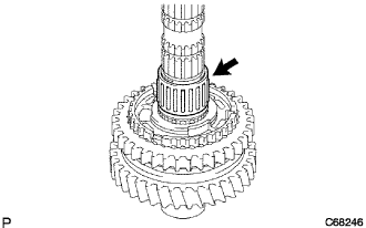
INSTALL REVERSE GEAR
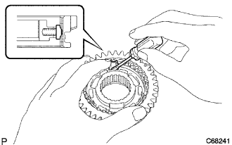
Coat the reverse gear with gear oil and install it onto the No. 1 transmission clutch hub.
NOTICE:
Orient the reverse gear and No. 1 transmission clutch hub correctly.
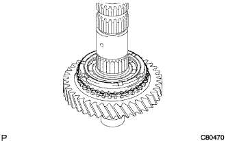
Install the 3 synchromesh shifting key springs and 3 synchromesh keys onto the No. 1 transmission clutch hub.
2.
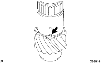
INSTALL 1ST GEAR THRUST WASHER PIN OR BALL
Coat the 1st gear thrust washer pin or ball with MP grease, and install it onto the output shaft.
3.
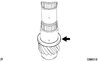
INSTALL 1ST GEAR THRUST WASHER
Coat the 1st gear thrust washer with gear oil and install it onto the output shaft.
4.
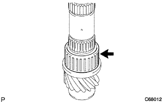
INSTALL 1ST GEAR NEEDLE ROLLER BEARING
Coat the 1st gear needle roller bearing with gear oil and install it onto the output shaft.
5.
INSTALL 1ST GEAR
Coat the 1st gear with gear oil and install it onto the output shaft.
6.
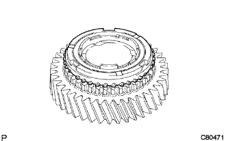
INSTALL NO. 1 SYNCHRONIZER RING (FOR 1ST GEAR)
Coat the No. 1 synchronizer ring with gear oil and install it onto the 1st gear.
7.
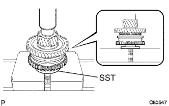
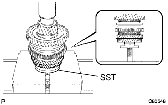
INSTALL NO. 1 TRANSMISSION CLUTCH HUB
Using SST and a press, install the No. 1 transmission clutch hub onto the output shaft.
SST
09316-60011
(09316-00031)
HINT:
The 1st gear can be turned.
While checking that the 1st gear thrust washer pin or ball is inserted into the groove of the 1st gear thrust washer, press and fit the No. 1 clutch hub.
Select a snap ring that will allow minimum axial play.
Standard clearance:
0.1 mm (0.039 in.) or less
Snap ring thickness:
Mark
Thickness mm (in.)
Mark
Thickness mm (in.)
A
2.50 (0.0984)
D
2.68 (0.1055)
B
2.56 (0.1008)
E
2.74 (0.1079)
C
2.62 (0.1031)
F
2.80 (0.1102)
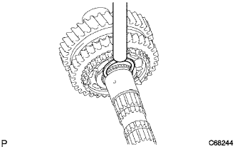
Using a brass bar and a hammer, install the snap ring onto the output shaft.
NOTICE:
Do not damage the journal surface of the output shaft.
8.
INSTALL 2ND GEAR NEEDLE ROLLER BEARING
Coat the 2nd gear needle roller bearing and 2nd gear bearing spacer with gear oil, and install them onto the output shaft.
9.
INSTALL NO. 1 SYNCHRONIZER RING (FOR 2ND GEAR)
Coat the No. 1 synchronizer ring with gear oil and install it onto the 2nd gear.
10.
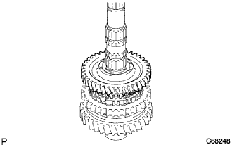
INSTALL 2ND GEAR
Coat the 2nd gear with gear oil and install it onto the output shaft.
11.
INSTALL 3RD DRIVEN GEAR
Using SST and a press, install the 3rd driven gear onto the output shaft.
SST
09316-60011
(09316-00031)
12.
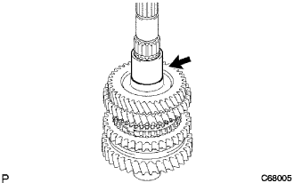
INSTALL OUTPUT GEAR SPACER
Install the output gear spacer onto the output shaft.
13.
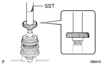
INSTALL 4TH DRIVEN GEAR
Using SST and a press, install the 4th driven gear onto the output shaft.
SST
09612-22011
14.
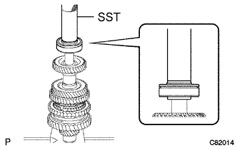
INSTALL OUTPUT SHAFT REAR BEARING
Using SST and a press, install the output shaft rear bearing onto the output shaft.
SST
09612-22011
15.
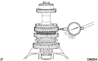
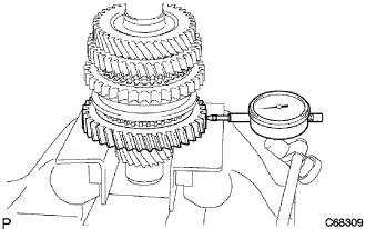
INSPECT 2ND GEAR RADIAL CLEARANCE
Using a dial gauge, measure the 2nd gear radial clearance between the gear and shaft.
Standard clearance:
KOYO made:
0.015 to 0.058 mm (0.0006 to 0.00023 in.)
NSK made:
0.015 to 0.056 mm (0.0006 to 0.0022 in.)
Maximum clearance:
KOYO made:
0.058 mm (0.0023 in.)
NSK made:
0.056 mm (0.0022 in.)
If the clearance exceeds the maximum, replace the 2nd gear or 2nd gear needle roller bearing.
16.
INSPECT 1ST GEAR RADIAL CLEARANCE
Using a dial gauge, measure the 1st gear radial clearance between the gear and shaft.
Standard clearance:
KOYO made:
0.015 to 0.058 mm (0.0006 to 0.00023 in.)
NSK made:
0.015 to 0.056 mm (0.0006 to 0.0022 in.)
Maximum clearance:
KOYO made:
0.058 mm (0.0023 in.)
NSK made:
0.056 mm (0.0022 in.)
If the clearance exceeds the maximum, replace the 1st gear or 1st gear needle roller bearing.
17.
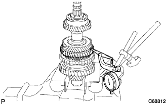
INSPECT 2ND GEAR THRUST CLEARANCE
Using a dial gauge, measure the 2nd gear thrust clearance.
Standard clearance:
0.10 to 0.55 mm (0.0039 to 0.0217 in.)
Maximum clearance:
0.55 mm (0.0217 in.)
If the clearance exceeds the maximum, replace the No. 1 transmission clutch hub, 2nd gear or 3rd driven gear.
18.
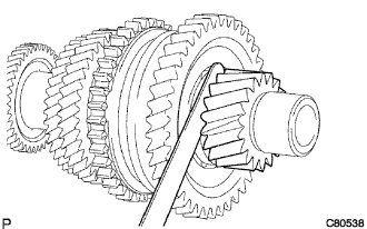
INSPECT 1ST GEAR THRUST CLEARANCE
Using a feeler gauge, measure the 1st gear thrust clearance.
Standard clearance:
0.10 to 0.40 mm (0.0039 to 0.0157 in.)
Maximum clearance:
0.40 mm (0.0157 in.)
If the clearance exceeds the maximum, replace the 1st gear thrust washer, 1st gear or No. 1 transmission clutch hub.