REMOVAL
Removal / installation · Vehicles built from Jan 2006
| 1. DISCONNECT CABLE FROM NEGATIVE BATTERY TERMINAL |
| 2. REMOVE FRONT WIPER ARM HEAD CAP |

Using a screwdriver with its tip wrapped in protective tape, disengage the claw and remove the 2 front wiper arm head caps.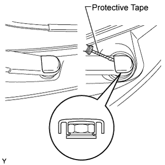

| 3. REMOVE FRONT WIPER ARM AND BLADE ASSEMBLY LH |
Operate the wiper, then stop the windshield wiper motor in the automatic stop position.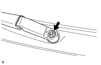
Remove the nut and front wiper arm.
| 4. REMOVE FRONT WIPER ARM AND BLADE ASSEMBLY RH |
- HINT:
- Use the same procedure as for the LH side.
| 5. REMOVE COWL SIDE VENTILATOR SUB-ASSEMBLY LH |
Using a screwdriver with its tip wrapped in protective tape, disengage the 3 claws and remove the cowl side ventilator sub-assembly LH.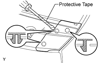
| 6. REMOVE COWL SIDE VENTILATOR SUB-ASSEMBLY RH |
- HINT:
- Use the same procedure as for the LH side.
| 7. REMOVE COWL TOP VENTILATOR LOUVER SUB-ASSEMBLY (for LHD) |
Disengage the 3 clips, the 4 claws and the 8 hooks.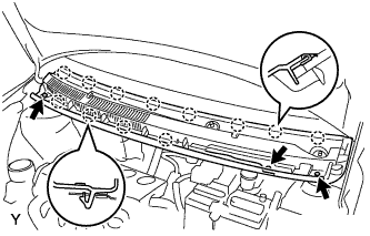
Remove the cowl top ventilator louver sub-assembly.
Disconnect the washer hoses.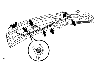
Disengage the 5 hooks.
| 8. REMOVE COWL TOP VENTILATOR LOUVER SUB-ASSEMBLY (for RHD) |
Disengage the 2 clips, the 6 claws and the 10 hooks.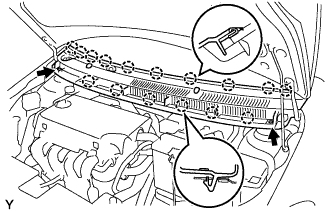
Remove the cowl top ventilator louver sub-assembly.
Disconnect the washer hoses.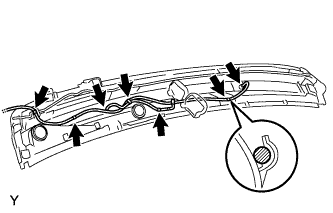
Disengage the 5 hooks.
| 9. REMOVE FRONT WIPER MOTOR AND LINK |
Remove the 2 bolts.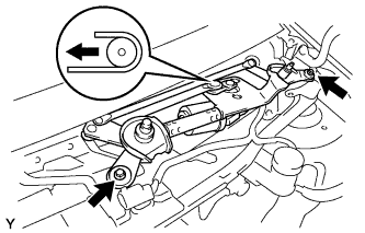
Slide the wiper link. Disengage the meshing of the rubber pin, then disconnect the connector and remove the front wiper motor and link.
| 10. REMOVE FRONT AIR SHUTTER SEAL |
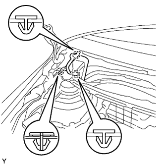 |
Disengage the 3 claws and remove the front air shutter seal.
| 11. REMOVE COWL TOP PANEL OUTER |
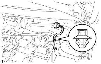 |
Disengage the wire harness clamp.
Remove the 2 bolts and remove the cowl top to cowl inner brace.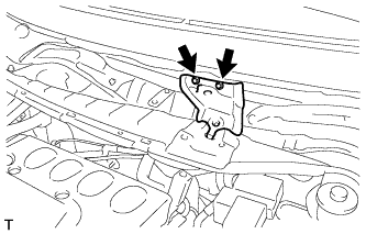
Remove the 8 bolts and remove the cowl top panel outer.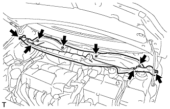
| 12. REMOVE FRONT WHEEL |
| 13. SEPARATE FRONT STABILIZER LINK ASSEMBLY |
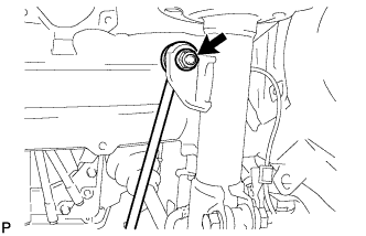 |
Remove the nut and separate the stabilizer link from the shock absorber.
- HINT:
- If the ball joint turns together with the nut, use a socket hexagon wrench 6 to hold the stud.
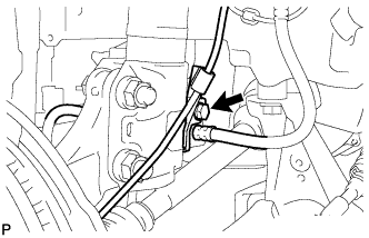
| 14. SEPARATE FRONT FLEXIBLE HOSE |
 |
w/ ABS:
Remove the bolt and separate the speed sensor and flexible hose.
w/o ABS:
Remove the bolt and separate the flexible hose.
| 15. REMOVE FRONT SUSPENSION SUPPORT DUST COVER |
| 16. REMOVE FRONT SHOCK ABSORBER WITH COIL SPRING |
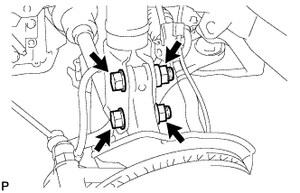 |
Remove the 2 nuts and 2 bolts and separate the shock absorber with coil spring from the steering knuckle.
- HINT:
- Keep the bolt from rotating while loosening and removing the nuts.
Using a socket hexagon wrench 6, fix the shock absorber rod and remove the nut.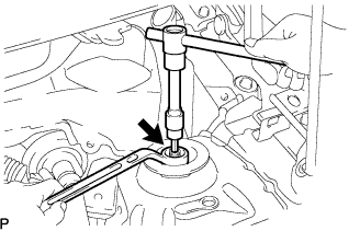
Remove the No. 2 suspension support.
Remove the front shock absorber with coil spring from the vehicle.