DISASSEMBLY
Removal / installation · Vehicles built from Aug 2005
| 1. REMOVE SPARK PLUG |

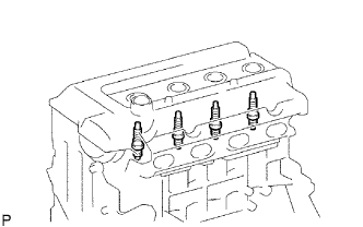  |
Using a spark plug wrench, remove the 4 spark plugs.
| 2. REMOVE KNOCK SENSOR |
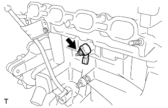 |
Remove the nut and remove the knock sensor.
| 3. REMOVE ENGINE OIL PRESSURE SWITCH ASSEMBLY |
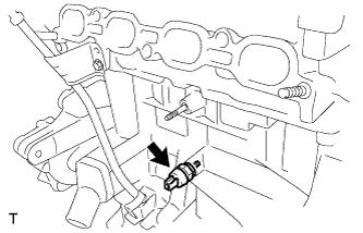 |
Using a 24 mm deep socket wrench, remove the oil pressure switch.
| 4. REMOVE ENGINE COOLANT TEMPERATURE SENSOR |
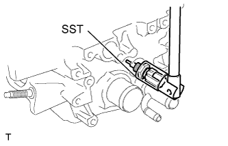 |
Using SST, remove the engine coolant temperature sensor.
- SST
- 09817-33190
| 5. REMOVE WATER INLET |
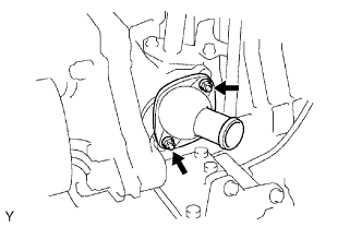 |
Remove the 2 nuts and remove the water inlet.
| 6. REMOVE THERMOSTAT |
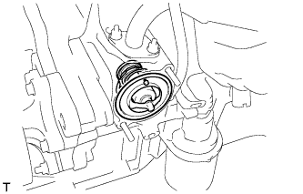 |
Remove the thermostat.
Remove the gasket from the thermostat.
| 7. REMOVE OIL FILLER CAP SUB-ASSEMBLY |
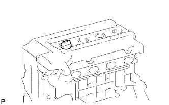 |
Remove the oil filler cap from the cylinder head cover.
| 8. REMOVE OIL FILLER CAP GASKET |
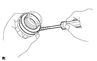 |
Using a screwdriver, remove the gasket from the oil filler cap.
| 9. REMOVE CRANKSHAFT POSITION SENSOR |
Remove the bolt and the crankshaft position sensor.
| 10. REMOVE VENTILATION VALVE SUB-ASSEMBLY |
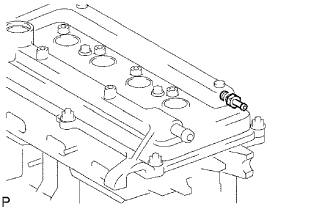 |
Remove the ventilation valve from the cylinder head cover.
| 11. REMOVE CYLINDER HEAD COVER SUB-ASSEMBLY |
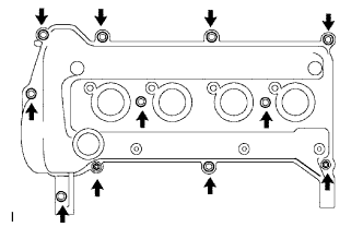 |
Remove the 9 bolts, 2 nuts and 2 seal washers and then remove the cylinder head cover sub-assembly.
| 12. REMOVE CYLINDER HEAD COVER GASKET |
Remove the gasket from the cylinder head cover.
| 13. REMOVE CAMSHAFT TIMING OIL CONTROL VALVE ASSEMBLY |
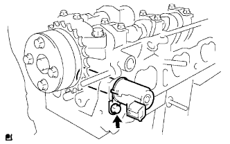 |
Remove the bolt and the camshaft timing oil control valve.
| 14. REMOVE OIL LEVEL GAUGE GUIDE |
Remove the bolt and the oil level gauge guide.
| 15. REMOVE WATER PUMP PULLEY |
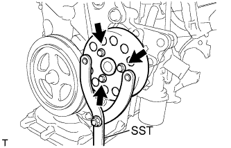 |
Using SST, hold the pump pulley.
- SST
- 09960-10010
(09962-01000, 09963-00700)
Remove the 3 bolts and the pump pulley.
| 16. REMOVE CRANKSHAFT DAMPER SUB-ASSEMBLY |
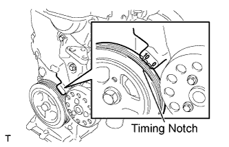 |
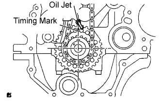
Set cylinder No. 1 to TDC/compression.
Turn the crankshaft damper sub-assembly, and align its timing notch with timing mark "0" of the oil pump.
Check that the timing marks on the camshaft timing sprocket and the camshaft timing gear are all facing upward, as shown in the illustration.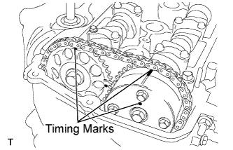
If not, turn the crankshaft 1 complete revolution (360°) and align the marks as above.
Using 2 SSTs, loosen the bolt while holding the crankshaft damper sub-assembly.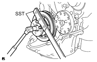
- SST
- 09213-14010
(91651-60865)
09330-00021
- NOTICE:
- Check the SST installation positions when installing them, to avoid the SST fixing bolts from coming into contact with the oil pump assembly.
Remove the SSTs and the bolt.
Remove the crankshaft damper sub-assembly.
| 17. REMOVE TRANSVERSE ENGINE ENGINE MOUNTING BRACKET |
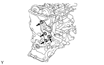 |
Remove the 4 bolts and remove the transverse engine mounting bracket.
| 18. REMOVE WATER PUMP ASSEMBLY |
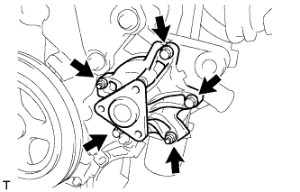 |
Remove the 3 bolts and 2 nuts and remove the water pump and gasket.
| 19. REMOVE OIL PUMP ASSEMBLY |
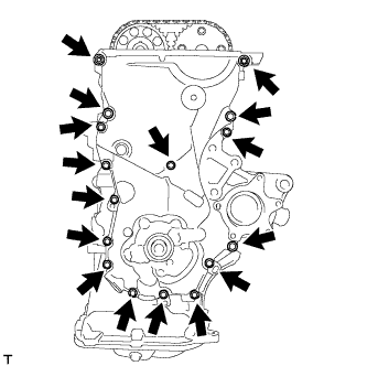 |
Remove the 15 bolts and nut.
Using a screwdriver with its tip wrapped in protective tape, prize the oil pump assembly to remove it.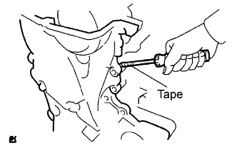
- NOTICE:
- Do not damage the contact surface of the oil pump assembly and oil pan sub-assembly.
Remove the 2 O-rings from the cylinder block and oil pan sub-assembly.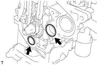
| 20. REMOVE OIL PUMP SEAL |
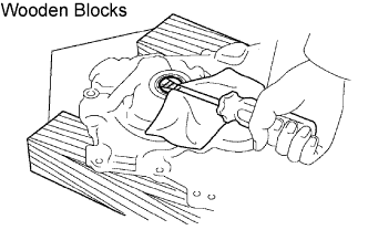 |
Using a screwdriver with its tip wrapped in protective tape, remove the oil seal.
| 21. REMOVE CHAIN TENSIONER ASSEMBLY NO. 1 |
 |
- NOTICE:
- Do not rotate the crankshaft with the chain tensioner removed.
- When rotating the camshaft with the timing chain removed, rotate the crankshaft counterclockwise 40° from the TDC first.
- Do not rotate the crankshaft with the chain tensioner removed.
Pull up the stopper plate and hold it with its lock released.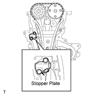
Unlock the plunger of the tensioner and push it in to the end.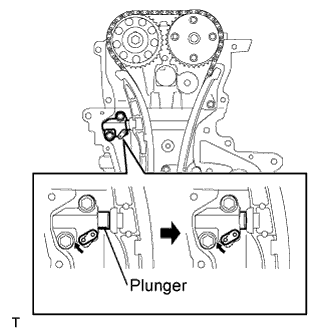
Pull down the stopper plate with the plunger pushed to the end and lock the plunger.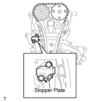
Insert a 3 mm (0.12 in.) diameter bar into the hole in the stopper plate and lock the plunger.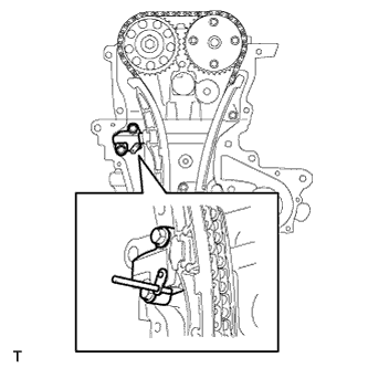
Remove the 2 bolts and remove chain tensioner assembly No. 1.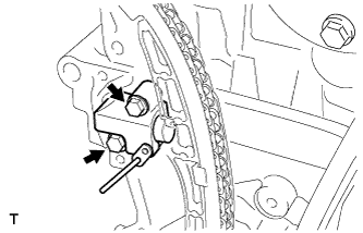
| 22. REMOVE CHAIN TENSIONER SLIPPER |
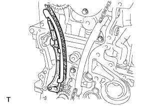 |
Remove the chain tensioner slipper.
| 23. REMOVE CHAIN VIBRATION DAMPER NO. 1 |
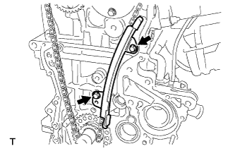 |
Remove the 2 bolts and remove chain vibration damper No. 1.
| 24. REMOVE CHAIN SUB-ASSEMBLY |
| 25. REMOVE FUEL DELIVERY PIPE SUB-ASSEMBLY |
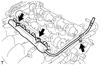 |
Remove the 3 bolts and remove the fuel delivery pipe sub-assembly together with the 4 fuel injectors.
- NOTICE:
- Do not drop the fuel injectors when removing the fuel delivery pipe sub-assembly.
| 26. REMOVE DELIVERY PIPE NO. 1 SPACER |
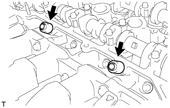 |
Remove the 2 delivery pipe No. 1 spacers.
| 27. REMOVE INJECTOR VIBRATION INSULATOR |
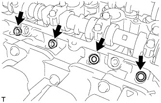 |
Remove the 4 injector vibration insulators.
| 28. REMOVE FUEL INJECTOR ASSEMBLY |
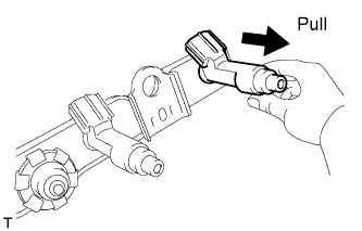 |
Pull the 4 fuel injector assemblies out of the fuel delivery pipe sub-assembly.
| 29. REMOVE CAMSHAFT POSITION SENSOR |
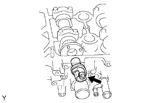 |
Remove the bolt and the camshaft position sensor.
| 30. REMOVE NO. 2 CAMSHAFT |
|
|
- NOTICE:
- When rotating the camshaft with the timing chain removed, rotate the crankshaft counterclockwise 40° from the TDC first, and align the oil jet hole with the paint mark. This prevents the pistons from coming into contact with the valves.
Using several steps, loosen and remove the 11 bearing cap bolts uniformly in the sequence shown in the illustration, then remove camshaft bearing cap No. 1, camshaft bearing cap No. 2 and camshaft No. 2.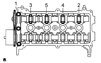
- NOTICE:
- Loosen each bolt uniformly while keeping the camshaft level.
| 31. REMOVE CAMSHAFT TIMING SPROCKET |
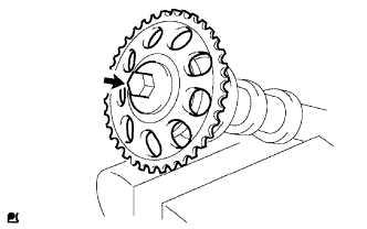 |
Clamp the camshaft in a vice.
Remove the flange bolt and the camshaft timing sprocket.
- NOTICE:
- Do not damage the camshaft.
| 32. REMOVE CAMSHAFT |
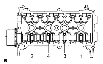 |
Using several steps, loosen and remove the 8 bearing cap bolts uniformly in the sequence shown in the illustration, then remove camshaft bearing cap No. 2 and the camshaft.
- NOTICE:
- Loosen each bolt uniformly keeping the camshaft level.
| 33. REMOVE CAMSHAFT TIMING GEAR ASSEMBLY |
Clamp the camshaft in a vise, and confirm that it is locked.
- NOTICE:
- Do not damage the camshaft.
Cover the 4 oil paths of the cam journal with tape as shown in the illustration.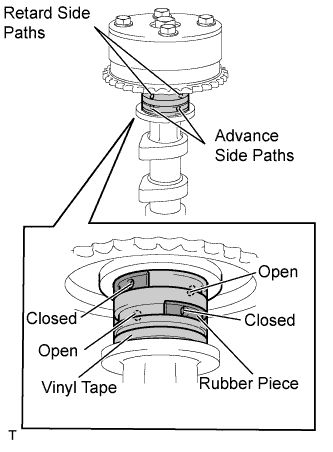
- HINT:
- One of the 2 grooves located on the cam journal is for retarding cam timing (upper) and the other is for advancing cam timing (lower). Each groove has 2 oil paths. Plug one of the oil paths for each groove with a piece rubber before wrapping the cam journal with the tape.
Puncture the tape covering the advance oil path and the retard oil path on the opposite side from the advance oil path.
Apply at about 150 kPa (1.5 kgf*cm2) air pressure into the 2 broken paths (the advance side path and the retard side path).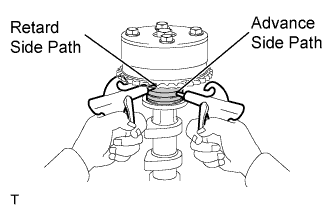
- NOTICE:
- Cover the paths with a shop rag or piece of cloth to prevent oil splashes.
Confirm that the camshaft timing gear assembly revolves in the timing advance direction when the air pressure on the timing retard path is reduced.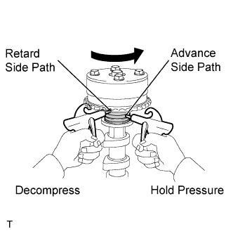
- HINT:
- The lock pin is released and the camshaft timing gear revolves in the advance direction.
When the camshaft timing gear reaches the most advanced position, release the air pressure on the timing retard side path, and then release the air pressure on the timing advance side path.
- NOTICE:
- Camshaft timing gear assembly occasionally shifts to the retard side abruptly if the air pressure on the advance side path is released first. It often results in the breakage of the lock pin.
Remove the flange bolt and remove the camshaft timing gear assembly.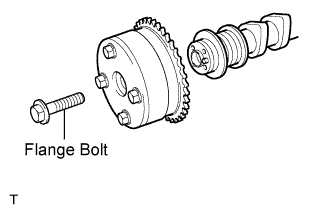
- NOTICE:
- Do not remove the other 4 bolts.
- When reusing the camshaft timing gear, unlock the lock pin inside the camshaft timing gear first.
- Do not remove the other 4 bolts.
| 34. REMOVE CYLINDER HEAD SUB-ASSEMBLY |
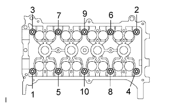 |
Using several steps, loosen and remove the 10 cylinder head bolts uniformly with an 8 mm bi-hexagon wrench in the sequence shown in the illustration. Remove the 10 cylinder head bolts and the plate washers.
- NOTICE:
- Do not drop the washers into the cylinder head.
- Head warpage or cracking could result from removing bolts in the wrong order.
- Do not drop the washers into the cylinder head.
| 35. REMOVE CYLINDER HEAD GASKET |
| 36. REMOVE OIL FILTER SUB-ASSEMBLY |
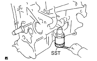 |
Using SST, remove the oil filter.
- SST
- 09228-06501
| 37. REMOVE OIL FILTER UNION |
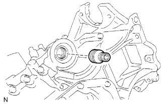 |
Using a 12 mm hexagon wrench, remove the oil filter union.
| 38. REMOVE ENGINE REAR OIL SEAL |
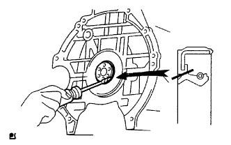 |
Using a knife, cut off the oil seal lip.
Using a screwdriver with its tip wrapped in tape, pry out the oil seal.
- NOTICE:
- After removal, check the crankshaft for any damage. If damaged, smooth the surface with 400-grit sandpaper.
| 39. REMOVE OIL PAN SUB-ASSEMBLY NO. 2 |
Remove the oil pan drain plug and gasket.
Remove the 9 bolts and 2 nuts.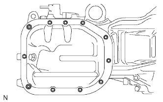
Insert the blade of SST between oil pan No. 1 and oil pan No. 2, and cut off the applied sealer and remove oil pan No. 2.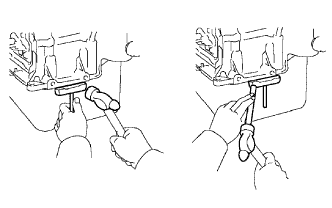
- SST
- 09032-00100
- NOTICE:
- Do not damage oil pan No. 1 or oil pan No. 2.
| 40. REMOVE OIL STRAINER SUB-ASSEMBLY |
Remove the bolt and 2 nuts.
Remove the oil strainer and the gasket.
| 41. REMOVE OIL PAN SUB-ASSEMBLY |
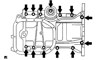 |
Loosen and remove the 13 bolts uniformly in several steps.
Using a screwdriver, remove oil pan No. 1 by prying between the cylinder block and oil pan No. 1.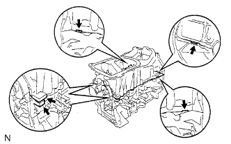
- NOTICE:
- Do not damage the contact surfaces of oil pan No. 1 or the cylinder block.
Remove the 2 O-rings from the cylinder block.
| 42. REMOVE STUD BOLT |
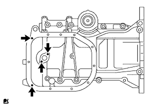 |
Remove the 4 stud bolts.
| 43. REMOVE PISTON SUB-ASSEMBLY WITH CONNECTING ROD |
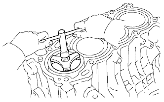 |
Using a ridge reamer, remove all the carbon from the top of the cylinder.
Push the piston, connecting the rod assembly and upper bearing through the top of the cylinder block to remove them.
- HINT:
- Keep the bearing, connecting rod and cap together.
- Keep the piston and the connecting rod assemblies in the correct order so that they can be returned to their original locations when reassembled.
- Keep the bearing, connecting rod and cap together.
| 44. REMOVE CONNECTING ROD BEARING |
| 45. REMOVE CRANKSHAFT |
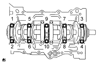 |
Using several steps, loosen and remove the 10 bearing cap sub-assembly bolts uniformly using SST in the sequence shown in the illustration.
- SST
- 09011-38121
Remove the bearing cap and the crankshaft.
| 46. REMOVE CRANKSHAFT BEARING |
| 47. REMOVE CRANKSHAFT THRUST WASHER UPPER |
| 48. REMOVE PISTON RING SET |
- NOTICE:
- Keep the piston rings in the correct combination and correct order so that they can be returned to their original locations when re-assembling.
Using a piston ring expander, remove the 2 compression rings.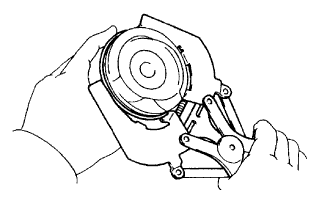
Remove the 2 side rails and the oil ring by hand.
| 49. REMOVE WITH PIN PISTON SUB-ASSEMBLY |
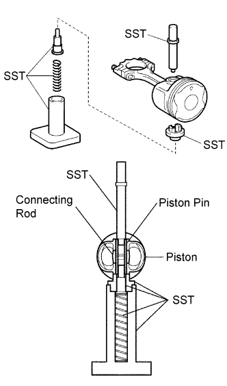 |
Using SST, press the piston pin out of the piston.
- SST
- 09221-25026
(09221-00021, 09221-00030, 09221-00090, 09221-00150, 09221-00100)
- NOTICE:
- Keep the pistons, pins, rings, connecting rods and bearings in the correct order so that they can be returned to their original locations when reassembled.
| 50. REMOVE CYLINDER BLOCK WATER DRAIN COCK SUB-ASSEMBLY |
| 51. REMOVE STUD BOLT |
Using "Torx" socket wrench E5, remove the 7 stud bolts.
| 52. REMOVE RING PIN |
| 53. REMOVE STRAIGHT PIN |