ON-VEHICLE INSPECTION
Inspection · Vehicles built from Aug 2005
| INSPECT TURN SIGNAL FLASHER CIRCUIT (for LHD) |

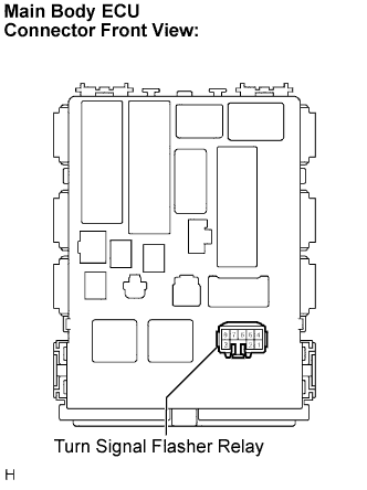  |
Check the power source circuit and ground circuit.
Remove the turn signal flasher relay from the main body ECU.
Measure the voltage and check the results in accordance with the value(s) in the table below.
- Standard Voltage:
Tester Connection
Condition
Specified Condition
1 - Body ground
Ignition switch off
0 V
1 - Body ground
Ignition switch on (IG)
10 to 14 V
4 - Body ground
Always
10 to 14 V
Measure the resistance and check the result in accordance with the value(s) in the table below.
- Standard Resistance:
Tester Connection
Condition
Specified Condition
7 - Body ground
Always
Below 1 Ω
Check the output operation signal.
Install the turn signal flasher relay onto the main body ECU.
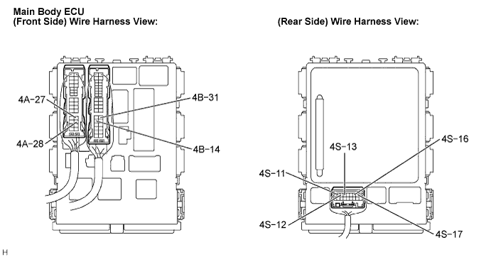
Measure the voltage and check the results in accordance with the values in the table below.
- Standard:
Tester Connection
Condition
Specified Condition
4A-27 - Body ground
Hazard warning switch OFF → ON
0 V → 10 to 14 V (60 to 120 times per minute)
4A-27 - Body ground
Turn signal switch (left turn) OFF → ON
0 V → 10 to 14 V (60 to 120 times per minute)
4A-28 - Body ground
Hazard warning switch OFF → ON
0 V → 10 to 14 V (60 to 120 times per minute)
4A-28 - Body ground
Turn signal switch (right turn) OFF → ON
0 V → 10 to 14 V (60 to 120 times per minute)
4B-14 - Body ground
Hazard warning switch OFF → ON
0 V → 10 to 14 V (60 to 120 times per minute)
4B-14 - Body ground
Turn signal switch (left turn) OFF → ON
0 V → 10 to 14 V (60 to 120 times per minute)
4B-31 - Body ground
Hazard warning switch OFF → ON
0 V → 10 to 14 V (60 to 120 times per minute)
4B-31 - Body ground
Turn signal switch (right turn) OFF → ON
0 V → 10 to 14 V (60 to 120 times per minute)
4S-11 - Body ground
Turn signal switch (left turn) OFF → ON
10 to 14 V → 0 V
4S-12 - Body ground
Turn signal switch (right turn) OFF → ON
10 to 14 V → 0 V
4S-13 - Body ground
Hazard warning switch OFF → ON
0 V → 10 to 14 V (60 to 120 times per minute)
4S-13 - Body ground
Turn signal switch (left turn) OFF → ON
0 V → 10 to 14 V (60 to 120 times per minute)
4S-16 - Body ground
Hazard warning switch OFF → ON
0 V → 10 to 14 V (60 to 120 times per minute)
4S-16 - Body ground
Turn signal switch (right turn) OFF → ON
0 V → 10 to 14 V (60 to 120 times per minute)
4S-17 - Body ground
Hazard warning switch OFF → ON
10 to 14 V → 0 V
| INSPECT TURN SIGNAL FLASHER CIRCUIT (for RHD) |
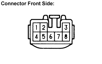 |
Check the power source circuit and ground circuit.
Remove the turn signal flasher assembly.
Measure the voltage and check the results in accordance with the value(s) in the table below.
- Standard Voltage:
Tester Connection
Condition
Specified Condition
1 - Body ground
Ignition switch off
0 V
1 - Body ground
Ignition switch on (IG)
10 to 14 V
4 - Body ground
Always
10 to 14 V
Measure the resistance and check the result in accordance with the value(s) in the table below.
- Standard Resistance:
Tester Connection
Condition
Specified Condition
7 - Body ground
Always
Below 1 Ω
Check the output operation signal.
Install the turn signal flasher assembly.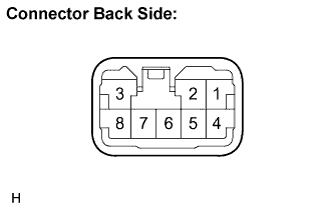
Measure the voltage and check the results in accordance with the value(s) in the table below.
- Standard:
Tester Connection
Condition
Specified Condition
2 - Body ground
Hazard warning switch OFF → ON
0 V → 10 to 14 V (60 to 120 times per minute)
2 - Body ground
Turn signal switch (right turn) OFF → ON
0 V → 10 to 14 V (60 to 120 times per minute)
3 - Body ground
Hazard warning switch OFF → ON
0 V → 10 to 14 V (60 to 120 times per minute)
3 - Body ground
Turn signal switch (left turn) OFF → ON
0 V → 10 to 14 V (60 to 120 times per minute)
5 - Body ground
Turn signal switch (left turn) OFF → ON
10 to 14 V → 0 V
6 - Body ground
Turn signal switch (right turn) OFF → ON
10 to 14 V → 0 V
8 - Body ground
Hazard warning switch OFF → ON
10 to 14 V → 0 V